А ты не на название скетча смотри, может IDE для программатора только один файл и создает ))
Ты наерна Краснодарскую сельхозакадемию закончил? Колись, там жеж си шарп в почёте
Я в политехе учился. Давно когда-то
Может) каждая модель МК AVR имеет две области памяти, одна из которых допускает одновременное чтение и запись. RWW и NRWW.
Загрузчик может обновлять сам себя.
Удивил. Вся область флэш перезаписываемая. Нужно только уметь ею пользоваться. Суть то во фьюзах))
Листинги:
Mega2560
Спойлер
C:\TEMP\arduino_build_452931\BlinkWithoutDelay.ino.elf:     file format elf32-avr

Sections:
Idx Name          Size      VMA       LMA       File off  Algn
  0 .data         00000000  00800200  00800200  00000630  2**0
                  CONTENTS, ALLOC, LOAD, DATA
  1 .text         000005bc  00000000  00000000  00000074  2**1
                  CONTENTS, ALLOC, LOAD, READONLY, CODE
  2 .bss          0000000f  00800200  00800200  00000630  2**0
                  ALLOC
  3 .comment      00000011  00000000  00000000  00000630  2**0
                  CONTENTS, READONLY
  4 .note.gnu.avr.deviceinfo 00000040  00000000  00000000  00000644  2**2
                  CONTENTS, READONLY
  5 .debug_aranges 00000088  00000000  00000000  00000688  2**3
                  CONTENTS, READONLY, DEBUGGING
  6 .debug_info   00001443  00000000  00000000  00000710  2**0
                  CONTENTS, READONLY, DEBUGGING
  7 .debug_abbrev 00000d53  00000000  00000000  00001b53  2**0
                  CONTENTS, READONLY, DEBUGGING
  8 .debug_line   000005d7  00000000  00000000  000028a6  2**0
                  CONTENTS, READONLY, DEBUGGING
  9 .debug_frame  0000005c  00000000  00000000  00002e80  2**2
                  CONTENTS, READONLY, DEBUGGING
 10 .debug_str    0000065e  00000000  00000000  00002edc  2**0
                  CONTENTS, READONLY, DEBUGGING
 11 .debug_loc    00000444  00000000  00000000  0000353a  2**0
                  CONTENTS, READONLY, DEBUGGING
 12 .debug_ranges 000000c8  00000000  00000000  0000397e  2**0
                  CONTENTS, READONLY, DEBUGGING

Disassembly of section .text:

00000000 <__vectors>:
   0:	0c 94 17 01 	jmp	0x22e	; 0x22e <__ctors_end>
   4:	0c 94 2b 01 	jmp	0x256	; 0x256 <__bad_interrupt>
   8:	0c 94 2b 01 	jmp	0x256	; 0x256 <__bad_interrupt>
   c:	0c 94 2b 01 	jmp	0x256	; 0x256 <__bad_interrupt>
  10:	0c 94 2b 01 	jmp	0x256	; 0x256 <__bad_interrupt>
  14:	0c 94 2b 01 	jmp	0x256	; 0x256 <__bad_interrupt>
  18:	0c 94 2b 01 	jmp	0x256	; 0x256 <__bad_interrupt>
  1c:	0c 94 2b 01 	jmp	0x256	; 0x256 <__bad_interrupt>
  20:	0c 94 2b 01 	jmp	0x256	; 0x256 <__bad_interrupt>
  24:	0c 94 2b 01 	jmp	0x256	; 0x256 <__bad_interrupt>
  28:	0c 94 2b 01 	jmp	0x256	; 0x256 <__bad_interrupt>
  2c:	0c 94 2b 01 	jmp	0x256	; 0x256 <__bad_interrupt>
  30:	0c 94 2b 01 	jmp	0x256	; 0x256 <__bad_interrupt>
  34:	0c 94 2b 01 	jmp	0x256	; 0x256 <__bad_interrupt>
  38:	0c 94 2b 01 	jmp	0x256	; 0x256 <__bad_interrupt>
  3c:	0c 94 2b 01 	jmp	0x256	; 0x256 <__bad_interrupt>
  40:	0c 94 2b 01 	jmp	0x256	; 0x256 <__bad_interrupt>
  44:	0c 94 2b 01 	jmp	0x256	; 0x256 <__bad_interrupt>
  48:	0c 94 2b 01 	jmp	0x256	; 0x256 <__bad_interrupt>
  4c:	0c 94 2b 01 	jmp	0x256	; 0x256 <__bad_interrupt>
  50:	0c 94 2b 01 	jmp	0x256	; 0x256 <__bad_interrupt>
  54:	0c 94 2b 01 	jmp	0x256	; 0x256 <__bad_interrupt>
  58:	0c 94 2b 01 	jmp	0x256	; 0x256 <__bad_interrupt>
  5c:	0c 94 2d 01 	jmp	0x25a	; 0x25a <__vector_23>
  60:	0c 94 2b 01 	jmp	0x256	; 0x256 <__bad_interrupt>
  64:	0c 94 2b 01 	jmp	0x256	; 0x256 <__bad_interrupt>
  68:	0c 94 2b 01 	jmp	0x256	; 0x256 <__bad_interrupt>
  6c:	0c 94 2b 01 	jmp	0x256	; 0x256 <__bad_interrupt>
  70:	0c 94 2b 01 	jmp	0x256	; 0x256 <__bad_interrupt>
  74:	0c 94 2b 01 	jmp	0x256	; 0x256 <__bad_interrupt>
  78:	0c 94 2b 01 	jmp	0x256	; 0x256 <__bad_interrupt>
  7c:	0c 94 2b 01 	jmp	0x256	; 0x256 <__bad_interrupt>
  80:	0c 94 2b 01 	jmp	0x256	; 0x256 <__bad_interrupt>
  84:	0c 94 2b 01 	jmp	0x256	; 0x256 <__bad_interrupt>
  88:	0c 94 2b 01 	jmp	0x256	; 0x256 <__bad_interrupt>
  8c:	0c 94 2b 01 	jmp	0x256	; 0x256 <__bad_interrupt>
  90:	0c 94 2b 01 	jmp	0x256	; 0x256 <__bad_interrupt>
  94:	0c 94 2b 01 	jmp	0x256	; 0x256 <__bad_interrupt>
  98:	0c 94 2b 01 	jmp	0x256	; 0x256 <__bad_interrupt>
  9c:	0c 94 2b 01 	jmp	0x256	; 0x256 <__bad_interrupt>
  a0:	0c 94 2b 01 	jmp	0x256	; 0x256 <__bad_interrupt>
  a4:	0c 94 2b 01 	jmp	0x256	; 0x256 <__bad_interrupt>
  a8:	0c 94 2b 01 	jmp	0x256	; 0x256 <__bad_interrupt>
  ac:	0c 94 2b 01 	jmp	0x256	; 0x256 <__bad_interrupt>
  b0:	0c 94 2b 01 	jmp	0x256	; 0x256 <__bad_interrupt>
  b4:	0c 94 2b 01 	jmp	0x256	; 0x256 <__bad_interrupt>
  b8:	0c 94 2b 01 	jmp	0x256	; 0x256 <__bad_interrupt>
  bc:	0c 94 2b 01 	jmp	0x256	; 0x256 <__bad_interrupt>
  c0:	0c 94 2b 01 	jmp	0x256	; 0x256 <__bad_interrupt>
  c4:	0c 94 2b 01 	jmp	0x256	; 0x256 <__bad_interrupt>
  c8:	0c 94 2b 01 	jmp	0x256	; 0x256 <__bad_interrupt>
  cc:	0c 94 2b 01 	jmp	0x256	; 0x256 <__bad_interrupt>
  d0:	0c 94 2b 01 	jmp	0x256	; 0x256 <__bad_interrupt>
  d4:	0c 94 2b 01 	jmp	0x256	; 0x256 <__bad_interrupt>
  d8:	0c 94 2b 01 	jmp	0x256	; 0x256 <__bad_interrupt>
  dc:	0c 94 2b 01 	jmp	0x256	; 0x256 <__bad_interrupt>
  e0:	0c 94 2b 01 	jmp	0x256	; 0x256 <__bad_interrupt>

000000e4 <__trampolines_start>:
  e4:	0c 94 72 02 	jmp	0x4e4	; 0x4e4 <__LOCK_REGION_LENGTH__+0xe4>
  e8:	0c 94 ce 02 	jmp	0x59c	; 0x59c <__LOCK_REGION_LENGTH__+0x19c>
  ec:	0c 94 a4 02 	jmp	0x548	; 0x548 <__LOCK_REGION_LENGTH__+0x148>
  f0:	0c 94 77 02 	jmp	0x4ee	; 0x4ee <__LOCK_REGION_LENGTH__+0xee>
  f4:	0c 94 c0 02 	jmp	0x580	; 0x580 <__LOCK_REGION_LENGTH__+0x180>
  f8:	0c 94 93 02 	jmp	0x526	; 0x526 <__LOCK_REGION_LENGTH__+0x126>
  fc:	0c 94 9b 02 	jmp	0x536	; 0x536 <__LOCK_REGION_LENGTH__+0x136>
 100:	0c 94 97 02 	jmp	0x52e	; 0x52e <__LOCK_REGION_LENGTH__+0x12e>
 104:	0c 94 b2 02 	jmp	0x564	; 0x564 <__LOCK_REGION_LENGTH__+0x164>
 108:	0c 94 ca 02 	jmp	0x594	; 0x594 <__LOCK_REGION_LENGTH__+0x194>
 10c:	0c 94 8f 02 	jmp	0x51e	; 0x51e <__LOCK_REGION_LENGTH__+0x11e>
 110:	0c 94 a8 02 	jmp	0x550	; 0x550 <__LOCK_REGION_LENGTH__+0x150>
 114:	0c 94 bc 02 	jmp	0x578	; 0x578 <__LOCK_REGION_LENGTH__+0x178>
 118:	0c 94 b6 02 	jmp	0x56c	; 0x56c <__LOCK_REGION_LENGTH__+0x16c>
 11c:	0c 94 ae 02 	jmp	0x55c	; 0x55c <__LOCK_REGION_LENGTH__+0x15c>
 120:	0c 94 9e 02 	jmp	0x53c	; 0x53c <__LOCK_REGION_LENGTH__+0x13c>
 124:	0c 94 c4 02 	jmp	0x588	; 0x588 <__LOCK_REGION_LENGTH__+0x188>

00000128 <__trampolines_end>:
 128:	00 00       	nop
 12a:	21 00       	.word	0x0021	; ????
 12c:	24 00       	.word	0x0024	; ????
 12e:	27 00       	.word	0x0027	; ????
 130:	2a 00       	.word	0x002a	; ????
 132:	2d 00       	.word	0x002d	; ????
 134:	30 00       	.word	0x0030	; ????
 136:	33 00       	.word	0x0033	; ????
 138:	01 01       	movw	r0, r2
 13a:	00 00       	nop
 13c:	04 01       	movw	r0, r8
 13e:	07 01       	movw	r0, r14
 140:	0a 01       	movw	r0, r20

00000142 <port_to_output_PGM>:
 142:	00 00 22 00 25 00 28 00 2b 00 2e 00 31 00 34 00     ..".%.(.+...1.4.
 152:	02 01 00 00 05 01 08 01 0b 01                       ..........

0000015c <digital_pin_to_port_PGM>:
 15c:	05 05 05 05 07 05 08 08 08 08 02 02 02 02 0a 0a     ................
 16c:	08 08 04 04 04 04 01 01 01 01 01 01 01 01 03 03     ................
 17c:	03 03 03 03 03 03 04 07 07 07 0c 0c 0c 0c 0c 0c     ................
 18c:	0c 0c 02 02 02 02 06 06 06 06 06 06 06 06 0b 0b     ................
 19c:	0b 0b 0b 0b 0b 0b                                   ......

000001a2 <digital_pin_to_bit_mask_PGM>:
 1a2:	01 02 10 20 20 08 08 10 20 40 10 20 40 80 02 01     ...  ... @. @...
 1b2:	02 01 08 04 02 01 01 02 04 08 10 20 40 80 80 40     ........... @..@
 1c2:	20 10 08 04 02 01 80 04 02 01 80 40 20 10 08 04      ..........@ ...
 1d2:	02 01 08 04 02 01 01 02 04 08 10 20 40 80 01 02     ........... @...
 1e2:	04 08 10 20 40 80                                   ... @.

000001e8 <digital_pin_to_timer_PGM>:
 1e8:	00 00 0a 0b 02 09 0c 0d 0e 08 07 03 04 01 00 00     ................
	...
 214:	12 11 10 00 00 00 00 00 00 00 00 00 00 00 00 00     ................
	...

0000022e <__ctors_end>:
 22e:	11 24       	eor	r1, r1
 230:	1f be       	out	0x3f, r1	; 63
 232:	cf ef       	ldi	r28, 0xFF	; 255
 234:	d1 e2       	ldi	r29, 0x21	; 33
 236:	de bf       	out	0x3e, r29	; 62
 238:	cd bf       	out	0x3d, r28	; 61
 23a:	00 e0       	ldi	r16, 0x00	; 0
 23c:	0c bf       	out	0x3c, r16	; 60

0000023e <__do_clear_bss>:
 23e:	22 e0       	ldi	r18, 0x02	; 2
 240:	a0 e0       	ldi	r26, 0x00	; 0
 242:	b2 e0       	ldi	r27, 0x02	; 2
 244:	01 c0       	rjmp	.+2      	; 0x248 <.do_clear_bss_start>

00000246 <.do_clear_bss_loop>:
 246:	1d 92       	st	X+, r1

00000248 <.do_clear_bss_start>:
 248:	af 30       	cpi	r26, 0x0F	; 15
 24a:	b2 07       	cpc	r27, r18
 24c:	e1 f7       	brne	.-8      	; 0x246 <.do_clear_bss_loop>
 24e:	0e 94 77 01 	call	0x2ee	; 0x2ee <main>
 252:	0c 94 dc 02 	jmp	0x5b8	; 0x5b8 <_exit>

00000256 <__bad_interrupt>:
 256:	0c 94 00 00 	jmp	0	; 0x0 <__vectors>

0000025a <__vector_23>:
#if defined(TIM0_OVF_vect)
ISR(TIM0_OVF_vect)
#else
ISR(TIMER0_OVF_vect)
#endif
{
 25a:	1f 92       	push	r1
 25c:	0f 92       	push	r0
 25e:	0f b6       	in	r0, 0x3f	; 63
 260:	0f 92       	push	r0
 262:	11 24       	eor	r1, r1
 264:	2f 93       	push	r18
 266:	3f 93       	push	r19
 268:	8f 93       	push	r24
 26a:	9f 93       	push	r25
 26c:	af 93       	push	r26
 26e:	bf 93       	push	r27
	// copy these to local variables so they can be stored in registers
	// (volatile variables must be read from memory on every access)
	unsigned long m = timer0_millis;
 270:	80 91 05 02 	lds	r24, 0x0205	; 0x800205 <timer0_millis>
 274:	90 91 06 02 	lds	r25, 0x0206	; 0x800206 <timer0_millis+0x1>
 278:	a0 91 07 02 	lds	r26, 0x0207	; 0x800207 <timer0_millis+0x2>
 27c:	b0 91 08 02 	lds	r27, 0x0208	; 0x800208 <timer0_millis+0x3>
	unsigned char f = timer0_fract;
 280:	30 91 04 02 	lds	r19, 0x0204	; 0x800204 <timer0_fract>

	m += MILLIS_INC;
	f += FRACT_INC;
 284:	23 e0       	ldi	r18, 0x03	; 3
 286:	23 0f       	add	r18, r19
	if (f >= FRACT_MAX) {
 288:	2d 37       	cpi	r18, 0x7D	; 125
 28a:	58 f5       	brcc	.+86     	; 0x2e2 <__vector_23+0x88>
	// copy these to local variables so they can be stored in registers
	// (volatile variables must be read from memory on every access)
	unsigned long m = timer0_millis;
	unsigned char f = timer0_fract;

	m += MILLIS_INC;
 28c:	01 96       	adiw	r24, 0x01	; 1
 28e:	a1 1d       	adc	r26, r1
 290:	b1 1d       	adc	r27, r1
	if (f >= FRACT_MAX) {
		f -= FRACT_MAX;
		m += 1;
	}

	timer0_fract = f;
 292:	20 93 04 02 	sts	0x0204, r18	; 0x800204 <timer0_fract>
	timer0_millis = m;
 296:	80 93 05 02 	sts	0x0205, r24	; 0x800205 <timer0_millis>
 29a:	90 93 06 02 	sts	0x0206, r25	; 0x800206 <timer0_millis+0x1>
 29e:	a0 93 07 02 	sts	0x0207, r26	; 0x800207 <timer0_millis+0x2>
 2a2:	b0 93 08 02 	sts	0x0208, r27	; 0x800208 <timer0_millis+0x3>
	timer0_overflow_count++;
 2a6:	80 91 00 02 	lds	r24, 0x0200	; 0x800200 <_edata>
 2aa:	90 91 01 02 	lds	r25, 0x0201	; 0x800201 <_edata+0x1>
 2ae:	a0 91 02 02 	lds	r26, 0x0202	; 0x800202 <_edata+0x2>
 2b2:	b0 91 03 02 	lds	r27, 0x0203	; 0x800203 <_edata+0x3>
 2b6:	01 96       	adiw	r24, 0x01	; 1
 2b8:	a1 1d       	adc	r26, r1
 2ba:	b1 1d       	adc	r27, r1
 2bc:	80 93 00 02 	sts	0x0200, r24	; 0x800200 <_edata>
 2c0:	90 93 01 02 	sts	0x0201, r25	; 0x800201 <_edata+0x1>
 2c4:	a0 93 02 02 	sts	0x0202, r26	; 0x800202 <_edata+0x2>
 2c8:	b0 93 03 02 	sts	0x0203, r27	; 0x800203 <_edata+0x3>
}
 2cc:	bf 91       	pop	r27
 2ce:	af 91       	pop	r26
 2d0:	9f 91       	pop	r25
 2d2:	8f 91       	pop	r24
 2d4:	3f 91       	pop	r19
 2d6:	2f 91       	pop	r18
 2d8:	0f 90       	pop	r0
 2da:	0f be       	out	0x3f, r0	; 63
 2dc:	0f 90       	pop	r0
 2de:	1f 90       	pop	r1
 2e0:	18 95       	reti
	unsigned char f = timer0_fract;

	m += MILLIS_INC;
	f += FRACT_INC;
	if (f >= FRACT_MAX) {
		f -= FRACT_MAX;
 2e2:	26 e8       	ldi	r18, 0x86	; 134
 2e4:	23 0f       	add	r18, r19
		m += 1;
 2e6:	02 96       	adiw	r24, 0x02	; 2
 2e8:	a1 1d       	adc	r26, r1
 2ea:	b1 1d       	adc	r27, r1
 2ec:	d2 cf       	rjmp	.-92     	; 0x292 <__vector_23+0x38>

000002ee <main>:

void init()
{
	// this needs to be called before setup() or some functions won't
	// work there
	sei();
 2ee:	78 94       	sei

	// on the ATmega168, timer 0 is also used for fast hardware pwm
	// (using phase-correct PWM would mean that timer 0 overflowed half as often
	// resulting in different millis() behavior on the ATmega8 and ATmega168)
#if defined(TCCR0A) && defined(WGM01)
	sbi(TCCR0A, WGM01);
 2f0:	84 b5       	in	r24, 0x24	; 36
 2f2:	82 60       	ori	r24, 0x02	; 2
 2f4:	84 bd       	out	0x24, r24	; 36
	sbi(TCCR0A, WGM00);
 2f6:	84 b5       	in	r24, 0x24	; 36
 2f8:	81 60       	ori	r24, 0x01	; 1
 2fa:	84 bd       	out	0x24, r24	; 36
	// this combination is for the standard atmega8
	sbi(TCCR0, CS01);
	sbi(TCCR0, CS00);
#elif defined(TCCR0B) && defined(CS01) && defined(CS00)
	// this combination is for the standard 168/328/1280/2560
	sbi(TCCR0B, CS01);
 2fc:	85 b5       	in	r24, 0x25	; 37
 2fe:	82 60       	ori	r24, 0x02	; 2
 300:	85 bd       	out	0x25, r24	; 37
	sbi(TCCR0B, CS00);
 302:	85 b5       	in	r24, 0x25	; 37
 304:	81 60       	ori	r24, 0x01	; 1
 306:	85 bd       	out	0x25, r24	; 37

	// enable timer 0 overflow interrupt
#if defined(TIMSK) && defined(TOIE0)
	sbi(TIMSK, TOIE0);
#elif defined(TIMSK0) && defined(TOIE0)
	sbi(TIMSK0, TOIE0);
 308:	80 91 6e 00 	lds	r24, 0x006E	; 0x80006e <__TEXT_REGION_LENGTH__+0x70006e>
 30c:	81 60       	ori	r24, 0x01	; 1
 30e:	80 93 6e 00 	sts	0x006E, r24	; 0x80006e <__TEXT_REGION_LENGTH__+0x70006e>
	// this is better for motors as it ensures an even waveform
	// note, however, that fast pwm mode can achieve a frequency of up
	// 8 MHz (with a 16 MHz clock) at 50% duty cycle

#if defined(TCCR1B) && defined(CS11) && defined(CS10)
	TCCR1B = 0;
 312:	10 92 81 00 	sts	0x0081, r1	; 0x800081 <__TEXT_REGION_LENGTH__+0x700081>

	// set timer 1 prescale factor to 64
	sbi(TCCR1B, CS11);
 316:	80 91 81 00 	lds	r24, 0x0081	; 0x800081 <__TEXT_REGION_LENGTH__+0x700081>
 31a:	82 60       	ori	r24, 0x02	; 2
 31c:	80 93 81 00 	sts	0x0081, r24	; 0x800081 <__TEXT_REGION_LENGTH__+0x700081>
#if F_CPU >= 8000000L
	sbi(TCCR1B, CS10);
 320:	80 91 81 00 	lds	r24, 0x0081	; 0x800081 <__TEXT_REGION_LENGTH__+0x700081>
 324:	81 60       	ori	r24, 0x01	; 1
 326:	80 93 81 00 	sts	0x0081, r24	; 0x800081 <__TEXT_REGION_LENGTH__+0x700081>
	sbi(TCCR1, CS10);
#endif
#endif
	// put timer 1 in 8-bit phase correct pwm mode
#if defined(TCCR1A) && defined(WGM10)
	sbi(TCCR1A, WGM10);
 32a:	80 91 80 00 	lds	r24, 0x0080	; 0x800080 <__TEXT_REGION_LENGTH__+0x700080>
 32e:	81 60       	ori	r24, 0x01	; 1
 330:	80 93 80 00 	sts	0x0080, r24	; 0x800080 <__TEXT_REGION_LENGTH__+0x700080>

	// set timer 2 prescale factor to 64
#if defined(TCCR2) && defined(CS22)
	sbi(TCCR2, CS22);
#elif defined(TCCR2B) && defined(CS22)
	sbi(TCCR2B, CS22);
 334:	80 91 b1 00 	lds	r24, 0x00B1	; 0x8000b1 <__TEXT_REGION_LENGTH__+0x7000b1>
 338:	84 60       	ori	r24, 0x04	; 4
 33a:	80 93 b1 00 	sts	0x00B1, r24	; 0x8000b1 <__TEXT_REGION_LENGTH__+0x7000b1>

	// configure timer 2 for phase correct pwm (8-bit)
#if defined(TCCR2) && defined(WGM20)
	sbi(TCCR2, WGM20);
#elif defined(TCCR2A) && defined(WGM20)
	sbi(TCCR2A, WGM20);
 33e:	80 91 b0 00 	lds	r24, 0x00B0	; 0x8000b0 <__TEXT_REGION_LENGTH__+0x7000b0>
 342:	81 60       	ori	r24, 0x01	; 1
 344:	80 93 b0 00 	sts	0x00B0, r24	; 0x8000b0 <__TEXT_REGION_LENGTH__+0x7000b0>
//#else
	// Timer 2 not finished (may not be present on this CPU)
#endif

#if defined(TCCR3B) && defined(CS31) && defined(WGM30)
	sbi(TCCR3B, CS31);		// set timer 3 prescale factor to 64
 348:	80 91 91 00 	lds	r24, 0x0091	; 0x800091 <__TEXT_REGION_LENGTH__+0x700091>
 34c:	82 60       	ori	r24, 0x02	; 2
 34e:	80 93 91 00 	sts	0x0091, r24	; 0x800091 <__TEXT_REGION_LENGTH__+0x700091>
	sbi(TCCR3B, CS30);
 352:	80 91 91 00 	lds	r24, 0x0091	; 0x800091 <__TEXT_REGION_LENGTH__+0x700091>
 356:	81 60       	ori	r24, 0x01	; 1
 358:	80 93 91 00 	sts	0x0091, r24	; 0x800091 <__TEXT_REGION_LENGTH__+0x700091>
	sbi(TCCR3A, WGM30);		// put timer 3 in 8-bit phase correct pwm mode
 35c:	80 91 90 00 	lds	r24, 0x0090	; 0x800090 <__TEXT_REGION_LENGTH__+0x700090>
 360:	81 60       	ori	r24, 0x01	; 1
 362:	80 93 90 00 	sts	0x0090, r24	; 0x800090 <__TEXT_REGION_LENGTH__+0x700090>
	sbi(TCCR4D, WGM40);		// put timer 4 in phase- and frequency-correct PWM mode
	sbi(TCCR4A, PWM4A);		// enable PWM mode for comparator OCR4A
	sbi(TCCR4C, PWM4D);		// enable PWM mode for comparator OCR4D
#else /* beginning of timer4 block for ATMEGA1280 and ATMEGA2560 */
#if defined(TCCR4B) && defined(CS41) && defined(WGM40)
	sbi(TCCR4B, CS41);		// set timer 4 prescale factor to 64
 366:	80 91 a1 00 	lds	r24, 0x00A1	; 0x8000a1 <__TEXT_REGION_LENGTH__+0x7000a1>
 36a:	82 60       	ori	r24, 0x02	; 2
 36c:	80 93 a1 00 	sts	0x00A1, r24	; 0x8000a1 <__TEXT_REGION_LENGTH__+0x7000a1>
	sbi(TCCR4B, CS40);
 370:	80 91 a1 00 	lds	r24, 0x00A1	; 0x8000a1 <__TEXT_REGION_LENGTH__+0x7000a1>
 374:	81 60       	ori	r24, 0x01	; 1
 376:	80 93 a1 00 	sts	0x00A1, r24	; 0x8000a1 <__TEXT_REGION_LENGTH__+0x7000a1>
	sbi(TCCR4A, WGM40);		// put timer 4 in 8-bit phase correct pwm mode
 37a:	80 91 a0 00 	lds	r24, 0x00A0	; 0x8000a0 <__TEXT_REGION_LENGTH__+0x7000a0>
 37e:	81 60       	ori	r24, 0x01	; 1
 380:	80 93 a0 00 	sts	0x00A0, r24	; 0x8000a0 <__TEXT_REGION_LENGTH__+0x7000a0>
#endif
#endif /* end timer4 block for ATMEGA1280/2560 and similar */

#if defined(TCCR5B) && defined(CS51) && defined(WGM50)
	sbi(TCCR5B, CS51);		// set timer 5 prescale factor to 64
 384:	80 91 21 01 	lds	r24, 0x0121	; 0x800121 <__TEXT_REGION_LENGTH__+0x700121>
 388:	82 60       	ori	r24, 0x02	; 2
 38a:	80 93 21 01 	sts	0x0121, r24	; 0x800121 <__TEXT_REGION_LENGTH__+0x700121>
	sbi(TCCR5B, CS50);
 38e:	80 91 21 01 	lds	r24, 0x0121	; 0x800121 <__TEXT_REGION_LENGTH__+0x700121>
 392:	81 60       	ori	r24, 0x01	; 1
 394:	80 93 21 01 	sts	0x0121, r24	; 0x800121 <__TEXT_REGION_LENGTH__+0x700121>
	sbi(TCCR5A, WGM50);		// put timer 5 in 8-bit phase correct pwm mode
 398:	80 91 20 01 	lds	r24, 0x0120	; 0x800120 <__TEXT_REGION_LENGTH__+0x700120>
 39c:	81 60       	ori	r24, 0x01	; 1
 39e:	80 93 20 01 	sts	0x0120, r24	; 0x800120 <__TEXT_REGION_LENGTH__+0x700120>
#endif

#if defined(ADCSRA)
	// set a2d prescaler so we are inside the desired 50-200 KHz range.
	#if F_CPU >= 16000000 // 16 MHz / 128 = 125 KHz
		sbi(ADCSRA, ADPS2);
 3a2:	80 91 7a 00 	lds	r24, 0x007A	; 0x80007a <__TEXT_REGION_LENGTH__+0x70007a>
 3a6:	84 60       	ori	r24, 0x04	; 4
 3a8:	80 93 7a 00 	sts	0x007A, r24	; 0x80007a <__TEXT_REGION_LENGTH__+0x70007a>
		sbi(ADCSRA, ADPS1);
 3ac:	80 91 7a 00 	lds	r24, 0x007A	; 0x80007a <__TEXT_REGION_LENGTH__+0x70007a>
 3b0:	82 60       	ori	r24, 0x02	; 2
 3b2:	80 93 7a 00 	sts	0x007A, r24	; 0x80007a <__TEXT_REGION_LENGTH__+0x70007a>
		sbi(ADCSRA, ADPS0);
 3b6:	80 91 7a 00 	lds	r24, 0x007A	; 0x80007a <__TEXT_REGION_LENGTH__+0x70007a>
 3ba:	81 60       	ori	r24, 0x01	; 1
 3bc:	80 93 7a 00 	sts	0x007A, r24	; 0x80007a <__TEXT_REGION_LENGTH__+0x70007a>
		cbi(ADCSRA, ADPS2);
		cbi(ADCSRA, ADPS1);
		sbi(ADCSRA, ADPS0);
	#endif
	// enable a2d conversions
	sbi(ADCSRA, ADEN);
 3c0:	80 91 7a 00 	lds	r24, 0x007A	; 0x80007a <__TEXT_REGION_LENGTH__+0x70007a>
 3c4:	80 68       	ori	r24, 0x80	; 128
 3c6:	80 93 7a 00 	sts	0x007A, r24	; 0x80007a <__TEXT_REGION_LENGTH__+0x70007a>
	// here so they can be used as normal digital i/o; they will be
	// reconnected in Serial.begin()
#if defined(UCSRB)
	UCSRB = 0;
#elif defined(UCSR0B)
	UCSR0B = 0;
 3ca:	10 92 c1 00 	sts	0x00C1, r1	; 0x8000c1 <__TEXT_REGION_LENGTH__+0x7000c1>
#include "wiring_private.h"
#include "pins_arduino.h"

void pinMode(uint8_t pin, uint8_t mode)
{
	uint8_t bit = digitalPinToBitMask(pin);
 3ce:	cf ea       	ldi	r28, 0xAF	; 175
 3d0:	d1 e0       	ldi	r29, 0x01	; 1
 3d2:	fe 01       	movw	r30, r28
 3d4:	24 91       	lpm	r18, Z
	uint8_t port = digitalPinToPort(pin);
 3d6:	09 e6       	ldi	r16, 0x69	; 105
 3d8:	11 e0       	ldi	r17, 0x01	; 1
 3da:	f8 01       	movw	r30, r16
 3dc:	84 91       	lpm	r24, Z
	volatile uint8_t *reg, *out;

	if (port == NOT_A_PIN) return;
 3de:	88 23       	and	r24, r24
 3e0:	99 f0       	breq	.+38     	; 0x408 <__LOCK_REGION_LENGTH__+0x8>

	// JWS: can I let the optimizer do this?
	reg = portModeRegister(port);
 3e2:	90 e0       	ldi	r25, 0x00	; 0
 3e4:	88 0f       	add	r24, r24
 3e6:	99 1f       	adc	r25, r25
 3e8:	fc 01       	movw	r30, r24
 3ea:	e8 5d       	subi	r30, 0xD8	; 216
 3ec:	fe 4f       	sbci	r31, 0xFE	; 254
 3ee:	a5 91       	lpm	r26, Z+
 3f0:	b4 91       	lpm	r27, Z
	out = portOutputRegister(port);
 3f2:	fc 01       	movw	r30, r24
 3f4:	ee 5b       	subi	r30, 0xBE	; 190
 3f6:	fe 4f       	sbci	r31, 0xFE	; 254
 3f8:	85 91       	lpm	r24, Z+
 3fa:	94 91       	lpm	r25, Z
                cli();
		*reg &= ~bit;
		*out |= bit;
		SREG = oldSREG;
	} else {
		uint8_t oldSREG = SREG;
 3fc:	8f b7       	in	r24, 0x3f	; 63
                cli();
 3fe:	f8 94       	cli
		*reg |= bit;
 400:	9c 91       	ld	r25, X
 402:	29 2b       	or	r18, r25
 404:	2c 93       	st	X, r18
		SREG = oldSREG;
 406:	8f bf       	out	0x3f, r24	; 63
	}
}

void digitalWrite(uint8_t pin, uint8_t val)
{
	uint8_t timer = digitalPinToTimer(pin);
 408:	95 ef       	ldi	r25, 0xF5	; 245
 40a:	c9 2e       	mov	r12, r25
 40c:	91 e0       	ldi	r25, 0x01	; 1
 40e:	d9 2e       	mov	r13, r25

	setup();

	for (;;) {
		loop();
		if (serialEventRun) serialEventRun();
 410:	20 e0       	ldi	r18, 0x00	; 0
 412:	e2 2e       	mov	r14, r18
 414:	20 e0       	ldi	r18, 0x00	; 0
 416:	f2 2e       	mov	r15, r18
    // save the last time you blinked the LED
    previousMillis = currentMillis;

    // if the LED is off turn it on and vice-versa:
    if (ledState == LOW) {
      ledState = HIGH;
 418:	aa 24       	eor	r10, r10
 41a:	a3 94       	inc	r10
 41c:	b1 2c       	mov	r11, r1
}

unsigned long millis()
{
	unsigned long m;
	uint8_t oldSREG = SREG;
 41e:	2f b7       	in	r18, 0x3f	; 63

	// disable interrupts while we read timer0_millis or we might get an
	// inconsistent value (e.g. in the middle of a write to timer0_millis)
	cli();
 420:	f8 94       	cli
	m = timer0_millis;
 422:	80 91 05 02 	lds	r24, 0x0205	; 0x800205 <timer0_millis>
 426:	90 91 06 02 	lds	r25, 0x0206	; 0x800206 <timer0_millis+0x1>
 42a:	a0 91 07 02 	lds	r26, 0x0207	; 0x800207 <timer0_millis+0x2>
 42e:	b0 91 08 02 	lds	r27, 0x0208	; 0x800208 <timer0_millis+0x3>
	SREG = oldSREG;
 432:	2f bf       	out	0x3f, r18	; 63
  // check to see if it's time to blink the LED; that is, if the difference
  // between the current time and last time you blinked the LED is bigger than
  // the interval at which you want to blink the LED.
  unsigned long currentMillis = millis();

  if (currentMillis - previousMillis >= interval) {
 434:	40 91 0b 02 	lds	r20, 0x020B	; 0x80020b <previousMillis>
 438:	50 91 0c 02 	lds	r21, 0x020C	; 0x80020c <previousMillis+0x1>
 43c:	60 91 0d 02 	lds	r22, 0x020D	; 0x80020d <previousMillis+0x2>
 440:	70 91 0e 02 	lds	r23, 0x020E	; 0x80020e <previousMillis+0x3>
 444:	3c 01       	movw	r6, r24
 446:	4d 01       	movw	r8, r26
 448:	64 1a       	sub	r6, r20
 44a:	75 0a       	sbc	r7, r21
 44c:	86 0a       	sbc	r8, r22
 44e:	97 0a       	sbc	r9, r23
 450:	b4 01       	movw	r22, r8
 452:	a3 01       	movw	r20, r6
 454:	48 3e       	cpi	r20, 0xE8	; 232
 456:	53 40       	sbci	r21, 0x03	; 3
 458:	61 05       	cpc	r22, r1
 45a:	71 05       	cpc	r23, r1
 45c:	08 f4       	brcc	.+2      	; 0x460 <__LOCK_REGION_LENGTH__+0x60>
 45e:	58 c0       	rjmp	.+176    	; 0x510 <__LOCK_REGION_LENGTH__+0x110>
    // save the last time you blinked the LED
    previousMillis = currentMillis;
 460:	80 93 0b 02 	sts	0x020B, r24	; 0x80020b <previousMillis>
 464:	90 93 0c 02 	sts	0x020C, r25	; 0x80020c <previousMillis+0x1>
 468:	a0 93 0d 02 	sts	0x020D, r26	; 0x80020d <previousMillis+0x2>
 46c:	b0 93 0e 02 	sts	0x020E, r27	; 0x80020e <previousMillis+0x3>

    // if the LED is off turn it on and vice-versa:
    if (ledState == LOW) {
 470:	80 91 09 02 	lds	r24, 0x0209	; 0x800209 <ledState>
 474:	90 91 0a 02 	lds	r25, 0x020A	; 0x80020a <ledState+0x1>
 478:	89 2b       	or	r24, r25
 47a:	09 f0       	breq	.+2      	; 0x47e <__LOCK_REGION_LENGTH__+0x7e>
 47c:	2e c0       	rjmp	.+92     	; 0x4da <__LOCK_REGION_LENGTH__+0xda>
      ledState = HIGH;
 47e:	b0 92 0a 02 	sts	0x020A, r11	; 0x80020a <ledState+0x1>
 482:	a0 92 09 02 	sts	0x0209, r10	; 0x800209 <ledState>
 486:	f6 01       	movw	r30, r12
 488:	84 91       	lpm	r24, Z
	uint8_t bit = digitalPinToBitMask(pin);
 48a:	fe 01       	movw	r30, r28
 48c:	24 91       	lpm	r18, Z
	uint8_t port = digitalPinToPort(pin);
 48e:	f8 01       	movw	r30, r16
 490:	94 91       	lpm	r25, Z
	volatile uint8_t *out;

	if (port == NOT_A_PIN) return;
 492:	99 23       	and	r25, r25
 494:	09 f4       	brne	.+2      	; 0x498 <__LOCK_REGION_LENGTH__+0x98>
 496:	3c c0       	rjmp	.+120    	; 0x510 <__LOCK_REGION_LENGTH__+0x110>
    } else {
      ledState = LOW;
    }

    // set the LED with the ledState of the variable:
    digitalWrite(ledPin, ledState);
 498:	30 91 09 02 	lds	r19, 0x0209	; 0x800209 <ledState>

	// If the pin that support PWM output, we need to turn it off
	// before doing a digital write.
	if (timer != NOT_ON_TIMER) turnOffPWM(timer);
 49c:	88 23       	and	r24, r24
 49e:	39 f1       	breq	.+78     	; 0x4ee <__LOCK_REGION_LENGTH__+0xee>
//
//static inline void turnOffPWM(uint8_t timer) __attribute__ ((always_inline));
//static inline void turnOffPWM(uint8_t timer)
static void turnOffPWM(uint8_t timer)
{
	switch (timer)
 4a0:	81 50       	subi	r24, 0x01	; 1
 4a2:	82 31       	cpi	r24, 0x12	; 18
 4a4:	20 f5       	brcc	.+72     	; 0x4ee <__LOCK_REGION_LENGTH__+0xee>
 4a6:	e8 2f       	mov	r30, r24
 4a8:	f0 e0       	ldi	r31, 0x00	; 0
 4aa:	88 27       	eor	r24, r24
 4ac:	e5 5a       	subi	r30, 0xA5	; 165
 4ae:	fd 4f       	sbci	r31, 0xFD	; 253
 4b0:	8f 4f       	sbci	r24, 0xFF	; 255
 4b2:	0c 94 d4 02 	jmp	0x5a8	; 0x5a8 <__tablejump2__>
 4b6:	97 02       	muls	r25, r23
 4b8:	9b 02       	muls	r25, r27
 4ba:	72 02       	muls	r23, r18
 4bc:	8f 02       	muls	r24, r31
 4be:	93 02       	muls	r25, r19
 4c0:	77 02       	muls	r23, r23
 4c2:	9e 02       	muls	r25, r30
 4c4:	a4 02       	muls	r26, r20
 4c6:	a8 02       	muls	r26, r24
 4c8:	ae 02       	muls	r26, r30
 4ca:	b2 02       	muls	r27, r18
 4cc:	b6 02       	muls	r27, r22
 4ce:	bc 02       	muls	r27, r28
 4d0:	c0 02       	muls	r28, r16
 4d2:	77 02       	muls	r23, r23
 4d4:	c4 02       	muls	r28, r20
 4d6:	ca 02       	muls	r28, r26
 4d8:	ce 02       	muls	r28, r30

    // if the LED is off turn it on and vice-versa:
    if (ledState == LOW) {
      ledState = HIGH;
    } else {
      ledState = LOW;
 4da:	10 92 0a 02 	sts	0x020A, r1	; 0x80020a <ledState+0x1>
 4de:	10 92 09 02 	sts	0x0209, r1	; 0x800209 <ledState>
 4e2:	d1 cf       	rjmp	.-94     	; 0x486 <__LOCK_REGION_LENGTH__+0x86>
	{
		#if defined(TCCR1A) && defined(COM1A1)
		case TIMER1A:   cbi(TCCR1A, COM1A1);    break;
 4e4:	80 91 80 00 	lds	r24, 0x0080	; 0x800080 <__TEXT_REGION_LENGTH__+0x700080>
 4e8:	8f 77       	andi	r24, 0x7F	; 127
		#endif
		#if defined(TCCR1A) && defined(COM1B1)
		case TIMER1B:   cbi(TCCR1A, COM1B1);    break;
		#endif
		#if defined(TCCR1A) && defined(COM1C1)
		case TIMER1C:   cbi(TCCR1A, COM1C1);    break;
 4ea:	80 93 80 00 	sts	0x0080, r24	; 0x800080 <__TEXT_REGION_LENGTH__+0x700080>

	// If the pin that support PWM output, we need to turn it off
	// before doing a digital write.
	if (timer != NOT_ON_TIMER) turnOffPWM(timer);

	out = portOutputRegister(port);
 4ee:	e9 2f       	mov	r30, r25
 4f0:	f0 e0       	ldi	r31, 0x00	; 0
 4f2:	ee 0f       	add	r30, r30
 4f4:	ff 1f       	adc	r31, r31
 4f6:	ee 5b       	subi	r30, 0xBE	; 190
 4f8:	fe 4f       	sbci	r31, 0xFE	; 254
 4fa:	a5 91       	lpm	r26, Z+
 4fc:	b4 91       	lpm	r27, Z

	uint8_t oldSREG = SREG;
 4fe:	8f b7       	in	r24, 0x3f	; 63
	cli();
 500:	f8 94       	cli

	if (val == LOW) {
		*out &= ~bit;
 502:	9c 91       	ld	r25, X
	out = portOutputRegister(port);

	uint8_t oldSREG = SREG;
	cli();

	if (val == LOW) {
 504:	31 11       	cpse	r19, r1
 506:	4e c0       	rjmp	.+156    	; 0x5a4 <__LOCK_REGION_LENGTH__+0x1a4>
		*out &= ~bit;
 508:	20 95       	com	r18
 50a:	29 23       	and	r18, r25
	} else {
		*out |= bit;
 50c:	2c 93       	st	X, r18
	}

	SREG = oldSREG;
 50e:	8f bf       	out	0x3f, r24	; 63
 510:	e1 14       	cp	r14, r1
 512:	f1 04       	cpc	r15, r1
 514:	09 f4       	brne	.+2      	; 0x518 <__LOCK_REGION_LENGTH__+0x118>
 516:	83 cf       	rjmp	.-250    	; 0x41e <__LOCK_REGION_LENGTH__+0x1e>
 518:	0e 94 00 00 	call	0	; 0x0 <__vectors>
 51c:	80 cf       	rjmp	.-256    	; 0x41e <__LOCK_REGION_LENGTH__+0x1e>
	{
		#if defined(TCCR1A) && defined(COM1A1)
		case TIMER1A:   cbi(TCCR1A, COM1A1);    break;
		#endif
		#if defined(TCCR1A) && defined(COM1B1)
		case TIMER1B:   cbi(TCCR1A, COM1B1);    break;
 51e:	80 91 80 00 	lds	r24, 0x0080	; 0x800080 <__TEXT_REGION_LENGTH__+0x700080>
 522:	8f 7d       	andi	r24, 0xDF	; 223
 524:	e2 cf       	rjmp	.-60     	; 0x4ea <__LOCK_REGION_LENGTH__+0xea>
		#endif
		#if defined(TCCR1A) && defined(COM1C1)
		case TIMER1C:   cbi(TCCR1A, COM1C1);    break;
 526:	80 91 80 00 	lds	r24, 0x0080	; 0x800080 <__TEXT_REGION_LENGTH__+0x700080>
 52a:	87 7f       	andi	r24, 0xF7	; 247
 52c:	de cf       	rjmp	.-68     	; 0x4ea <__LOCK_REGION_LENGTH__+0xea>
		#if defined(TCCR2) && defined(COM21)
		case  TIMER2:   cbi(TCCR2, COM21);      break;
		#endif

		#if defined(TCCR0A) && defined(COM0A1)
		case  TIMER0A:  cbi(TCCR0A, COM0A1);    break;
 52e:	84 b5       	in	r24, 0x24	; 36
 530:	8f 77       	andi	r24, 0x7F	; 127
		#endif

		#if defined(TCCR0A) && defined(COM0B1)
		case  TIMER0B:  cbi(TCCR0A, COM0B1);    break;
 532:	84 bd       	out	0x24, r24	; 36
 534:	dc cf       	rjmp	.-72     	; 0x4ee <__LOCK_REGION_LENGTH__+0xee>
 536:	84 b5       	in	r24, 0x24	; 36
 538:	8f 7d       	andi	r24, 0xDF	; 223
 53a:	fb cf       	rjmp	.-10     	; 0x532 <__LOCK_REGION_LENGTH__+0x132>
		#endif
		#if defined(TCCR2A) && defined(COM2A1)
		case  TIMER2A:  cbi(TCCR2A, COM2A1);    break;
 53c:	80 91 b0 00 	lds	r24, 0x00B0	; 0x8000b0 <__TEXT_REGION_LENGTH__+0x7000b0>
 540:	8f 77       	andi	r24, 0x7F	; 127
		#endif
		#if defined(TCCR2A) && defined(COM2B1)
		case  TIMER2B:  cbi(TCCR2A, COM2B1);    break;
 542:	80 93 b0 00 	sts	0x00B0, r24	; 0x8000b0 <__TEXT_REGION_LENGTH__+0x7000b0>
 546:	d3 cf       	rjmp	.-90     	; 0x4ee <__LOCK_REGION_LENGTH__+0xee>
 548:	80 91 b0 00 	lds	r24, 0x00B0	; 0x8000b0 <__TEXT_REGION_LENGTH__+0x7000b0>
 54c:	8f 7d       	andi	r24, 0xDF	; 223
 54e:	f9 cf       	rjmp	.-14     	; 0x542 <__LOCK_REGION_LENGTH__+0x142>
		#endif

		#if defined(TCCR3A) && defined(COM3A1)
		case  TIMER3A:  cbi(TCCR3A, COM3A1);    break;
 550:	80 91 90 00 	lds	r24, 0x0090	; 0x800090 <__TEXT_REGION_LENGTH__+0x700090>
 554:	8f 77       	andi	r24, 0x7F	; 127
		#endif
		#if defined(TCCR3A) && defined(COM3B1)
		case  TIMER3B:  cbi(TCCR3A, COM3B1);    break;
		#endif
		#if defined(TCCR3A) && defined(COM3C1)
		case  TIMER3C:  cbi(TCCR3A, COM3C1);    break;
 556:	80 93 90 00 	sts	0x0090, r24	; 0x800090 <__TEXT_REGION_LENGTH__+0x700090>
 55a:	c9 cf       	rjmp	.-110    	; 0x4ee <__LOCK_REGION_LENGTH__+0xee>

		#if defined(TCCR3A) && defined(COM3A1)
		case  TIMER3A:  cbi(TCCR3A, COM3A1);    break;
		#endif
		#if defined(TCCR3A) && defined(COM3B1)
		case  TIMER3B:  cbi(TCCR3A, COM3B1);    break;
 55c:	80 91 90 00 	lds	r24, 0x0090	; 0x800090 <__TEXT_REGION_LENGTH__+0x700090>
 560:	8f 7d       	andi	r24, 0xDF	; 223
 562:	f9 cf       	rjmp	.-14     	; 0x556 <__LOCK_REGION_LENGTH__+0x156>
		#endif
		#if defined(TCCR3A) && defined(COM3C1)
		case  TIMER3C:  cbi(TCCR3A, COM3C1);    break;
 564:	80 91 90 00 	lds	r24, 0x0090	; 0x800090 <__TEXT_REGION_LENGTH__+0x700090>
 568:	87 7f       	andi	r24, 0xF7	; 247
 56a:	f5 cf       	rjmp	.-22     	; 0x556 <__LOCK_REGION_LENGTH__+0x156>
		#endif

		#if defined(TCCR4A) && defined(COM4A1)
		case  TIMER4A:  cbi(TCCR4A, COM4A1);    break;
 56c:	80 91 a0 00 	lds	r24, 0x00A0	; 0x8000a0 <__TEXT_REGION_LENGTH__+0x7000a0>
 570:	8f 77       	andi	r24, 0x7F	; 127
		#endif
		#if defined(TCCR4A) && defined(COM4B1)
		case  TIMER4B:  cbi(TCCR4A, COM4B1);    break;
		#endif
		#if defined(TCCR4A) && defined(COM4C1)
		case  TIMER4C:  cbi(TCCR4A, COM4C1);    break;
 572:	80 93 a0 00 	sts	0x00A0, r24	; 0x8000a0 <__TEXT_REGION_LENGTH__+0x7000a0>
 576:	bb cf       	rjmp	.-138    	; 0x4ee <__LOCK_REGION_LENGTH__+0xee>

		#if defined(TCCR4A) && defined(COM4A1)
		case  TIMER4A:  cbi(TCCR4A, COM4A1);    break;
		#endif
		#if defined(TCCR4A) && defined(COM4B1)
		case  TIMER4B:  cbi(TCCR4A, COM4B1);    break;
 578:	80 91 a0 00 	lds	r24, 0x00A0	; 0x8000a0 <__TEXT_REGION_LENGTH__+0x7000a0>
 57c:	8f 7d       	andi	r24, 0xDF	; 223
 57e:	f9 cf       	rjmp	.-14     	; 0x572 <__LOCK_REGION_LENGTH__+0x172>
		#endif
		#if defined(TCCR4A) && defined(COM4C1)
		case  TIMER4C:  cbi(TCCR4A, COM4C1);    break;
 580:	80 91 a0 00 	lds	r24, 0x00A0	; 0x8000a0 <__TEXT_REGION_LENGTH__+0x7000a0>
 584:	87 7f       	andi	r24, 0xF7	; 247
 586:	f5 cf       	rjmp	.-22     	; 0x572 <__LOCK_REGION_LENGTH__+0x172>
		#if defined(TCCR4C) && defined(COM4D1)
		case TIMER4D:	cbi(TCCR4C, COM4D1);	break;
		#endif

		#if defined(TCCR5A)
		case  TIMER5A:  cbi(TCCR5A, COM5A1);    break;
 588:	80 91 20 01 	lds	r24, 0x0120	; 0x800120 <__TEXT_REGION_LENGTH__+0x700120>
 58c:	8f 77       	andi	r24, 0x7F	; 127
		case  TIMER5B:  cbi(TCCR5A, COM5B1);    break;
		case  TIMER5C:  cbi(TCCR5A, COM5C1);    break;
 58e:	80 93 20 01 	sts	0x0120, r24	; 0x800120 <__TEXT_REGION_LENGTH__+0x700120>
 592:	ad cf       	rjmp	.-166    	; 0x4ee <__LOCK_REGION_LENGTH__+0xee>
		case TIMER4D:	cbi(TCCR4C, COM4D1);	break;
		#endif

		#if defined(TCCR5A)
		case  TIMER5A:  cbi(TCCR5A, COM5A1);    break;
		case  TIMER5B:  cbi(TCCR5A, COM5B1);    break;
 594:	80 91 20 01 	lds	r24, 0x0120	; 0x800120 <__TEXT_REGION_LENGTH__+0x700120>
 598:	8f 7d       	andi	r24, 0xDF	; 223
 59a:	f9 cf       	rjmp	.-14     	; 0x58e <__LOCK_REGION_LENGTH__+0x18e>
		case  TIMER5C:  cbi(TCCR5A, COM5C1);    break;
 59c:	80 91 20 01 	lds	r24, 0x0120	; 0x800120 <__TEXT_REGION_LENGTH__+0x700120>
 5a0:	87 7f       	andi	r24, 0xF7	; 247
 5a2:	f5 cf       	rjmp	.-22     	; 0x58e <__LOCK_REGION_LENGTH__+0x18e>
	cli();

	if (val == LOW) {
		*out &= ~bit;
	} else {
		*out |= bit;
 5a4:	29 2b       	or	r18, r25
 5a6:	b2 cf       	rjmp	.-156    	; 0x50c <__LOCK_REGION_LENGTH__+0x10c>

000005a8 <__tablejump2__>:
 5a8:	ee 0f       	add	r30, r30
 5aa:	ff 1f       	adc	r31, r31
 5ac:	88 1f       	adc	r24, r24
 5ae:	8b bf       	out	0x3b, r24	; 59
 5b0:	07 90       	elpm	r0, Z+
 5b2:	f6 91       	elpm	r31, Z
 5b4:	e0 2d       	mov	r30, r0
 5b6:	19 94       	eijmp

000005b8 <_exit>:
 5b8:	f8 94       	cli

000005ba <__stop_program>:
 5ba:	ff cf       	rjmp	.-2      	; 0x5ba <__stop_program>
NANO
Спойлер
C:\TEMP\arduino_build_452931\BlinkWithoutDelay.ino.elf:     file format elf32-avr

Sections:
Idx Name          Size      VMA       LMA       File off  Algn
  0 .data         00000000  00800100  00800100  000003d0  2**0
                  CONTENTS, ALLOC, LOAD, DATA
  1 .text         0000035c  00000000  00000000  00000074  2**1
                  CONTENTS, ALLOC, LOAD, READONLY, CODE
  2 .bss          0000000f  00800100  00800100  000003d0  2**0
                  ALLOC
  3 .comment      00000011  00000000  00000000  000003d0  2**0
                  CONTENTS, READONLY
  4 .note.gnu.avr.deviceinfo 00000040  00000000  00000000  000003e4  2**2
                  CONTENTS, READONLY
  5 .debug_aranges 00000068  00000000  00000000  00000428  2**3
                  CONTENTS, READONLY, DEBUGGING
  6 .debug_info   00000de5  00000000  00000000  00000490  2**0
                  CONTENTS, READONLY, DEBUGGING
  7 .debug_abbrev 000007b8  00000000  00000000  00001275  2**0
                  CONTENTS, READONLY, DEBUGGING
  8 .debug_line   000004cf  00000000  00000000  00001a2d  2**0
                  CONTENTS, READONLY, DEBUGGING
  9 .debug_frame  0000005c  00000000  00000000  00001efc  2**2
                  CONTENTS, READONLY, DEBUGGING
 10 .debug_str    00000492  00000000  00000000  00001f58  2**0
                  CONTENTS, READONLY, DEBUGGING
 11 .debug_loc    0000042f  00000000  00000000  000023ea  2**0
                  CONTENTS, READONLY, DEBUGGING
 12 .debug_ranges 000000b0  00000000  00000000  00002819  2**0
                  CONTENTS, READONLY, DEBUGGING

Disassembly of section .text:

00000000 <__vectors>:
   0:	0c 94 5c 00 	jmp	0xb8	; 0xb8 <__ctors_end>
   4:	0c 94 6e 00 	jmp	0xdc	; 0xdc <__bad_interrupt>
   8:	0c 94 6e 00 	jmp	0xdc	; 0xdc <__bad_interrupt>
   c:	0c 94 6e 00 	jmp	0xdc	; 0xdc <__bad_interrupt>
  10:	0c 94 6e 00 	jmp	0xdc	; 0xdc <__bad_interrupt>
  14:	0c 94 6e 00 	jmp	0xdc	; 0xdc <__bad_interrupt>
  18:	0c 94 6e 00 	jmp	0xdc	; 0xdc <__bad_interrupt>
  1c:	0c 94 6e 00 	jmp	0xdc	; 0xdc <__bad_interrupt>
  20:	0c 94 6e 00 	jmp	0xdc	; 0xdc <__bad_interrupt>
  24:	0c 94 6e 00 	jmp	0xdc	; 0xdc <__bad_interrupt>
  28:	0c 94 6e 00 	jmp	0xdc	; 0xdc <__bad_interrupt>
  2c:	0c 94 6e 00 	jmp	0xdc	; 0xdc <__bad_interrupt>
  30:	0c 94 6e 00 	jmp	0xdc	; 0xdc <__bad_interrupt>
  34:	0c 94 6e 00 	jmp	0xdc	; 0xdc <__bad_interrupt>
  38:	0c 94 6e 00 	jmp	0xdc	; 0xdc <__bad_interrupt>
  3c:	0c 94 6e 00 	jmp	0xdc	; 0xdc <__bad_interrupt>
  40:	0c 94 70 00 	jmp	0xe0	; 0xe0 <__vector_16>
  44:	0c 94 6e 00 	jmp	0xdc	; 0xdc <__bad_interrupt>
  48:	0c 94 6e 00 	jmp	0xdc	; 0xdc <__bad_interrupt>
  4c:	0c 94 6e 00 	jmp	0xdc	; 0xdc <__bad_interrupt>
  50:	0c 94 6e 00 	jmp	0xdc	; 0xdc <__bad_interrupt>
  54:	0c 94 6e 00 	jmp	0xdc	; 0xdc <__bad_interrupt>
  58:	0c 94 6e 00 	jmp	0xdc	; 0xdc <__bad_interrupt>
  5c:	0c 94 6e 00 	jmp	0xdc	; 0xdc <__bad_interrupt>
  60:	0c 94 6e 00 	jmp	0xdc	; 0xdc <__bad_interrupt>
  64:	0c 94 6e 00 	jmp	0xdc	; 0xdc <__bad_interrupt>

00000068 <__trampolines_end>:
  68:	00 00       	nop
  6a:	00 00       	nop
  6c:	24 00       	.word	0x0024	; ????
  6e:	27 00       	.word	0x0027	; ????
  70:	2a 00       	.word	0x002a	; ????

00000072 <port_to_output_PGM>:
  72:	00 00 00 00 25 00 28 00 2b 00                       ....%.(.+.

0000007c <digital_pin_to_port_PGM>:
  7c:	04 04 04 04 04 04 04 04 02 02 02 02 02 02 03 03     ................
  8c:	03 03 03 03                                         ....

00000090 <digital_pin_to_bit_mask_PGM>:
  90:	01 02 04 08 10 20 40 80 01 02 04 08 10 20 01 02     ..... @...... ..
  a0:	04 08 10 20                                         ...

000000a4 <digital_pin_to_timer_PGM>:
  a4:	00 00 00 08 00 02 01 00 00 03 04 07 00 00 00 00     ................
  b4:	00 00 00 00                                         ....

000000b8 <__ctors_end>:
  b8:	11 24       	eor	r1, r1
  ba:	1f be       	out	0x3f, r1	; 63
  bc:	cf ef       	ldi	r28, 0xFF	; 255
  be:	d8 e0       	ldi	r29, 0x08	; 8
  c0:	de bf       	out	0x3e, r29	; 62
  c2:	cd bf       	out	0x3d, r28	; 61

000000c4 <__do_clear_bss>:
  c4:	21 e0       	ldi	r18, 0x01	; 1
  c6:	a0 e0       	ldi	r26, 0x00	; 0
  c8:	b1 e0       	ldi	r27, 0x01	; 1
  ca:	01 c0       	rjmp	.+2      	; 0xce <.do_clear_bss_start>

000000cc <.do_clear_bss_loop>:
  cc:	1d 92       	st	X+, r1

000000ce <.do_clear_bss_start>:
  ce:	af 30       	cpi	r26, 0x0F	; 15
  d0:	b2 07       	cpc	r27, r18
  d2:	e1 f7       	brne	.-8      	; 0xcc <.do_clear_bss_loop>
  d4:	0e 94 ba 00 	call	0x174	; 0x174 <main>
  d8:	0c 94 ac 01 	jmp	0x358	; 0x358 <_exit>

000000dc <__bad_interrupt>:
  dc:	0c 94 00 00 	jmp	0	; 0x0 <__vectors>

000000e0 <__vector_16>:
#if defined(TIM0_OVF_vect)
ISR(TIM0_OVF_vect)
#else
ISR(TIMER0_OVF_vect)
#endif
{
  e0:	1f 92       	push	r1
  e2:	0f 92       	push	r0
  e4:	0f b6       	in	r0, 0x3f	; 63
  e6:	0f 92       	push	r0
  e8:	11 24       	eor	r1, r1
  ea:	2f 93       	push	r18
  ec:	3f 93       	push	r19
  ee:	8f 93       	push	r24
  f0:	9f 93       	push	r25
  f2:	af 93       	push	r26
  f4:	bf 93       	push	r27
	// copy these to local variables so they can be stored in registers
	// (volatile variables must be read from memory on every access)
	unsigned long m = timer0_millis;
  f6:	80 91 05 01 	lds	r24, 0x0105	; 0x800105 <timer0_millis>
  fa:	90 91 06 01 	lds	r25, 0x0106	; 0x800106 <timer0_millis+0x1>
  fe:	a0 91 07 01 	lds	r26, 0x0107	; 0x800107 <timer0_millis+0x2>
 102:	b0 91 08 01 	lds	r27, 0x0108	; 0x800108 <timer0_millis+0x3>
	unsigned char f = timer0_fract;
 106:	30 91 04 01 	lds	r19, 0x0104	; 0x800104 <timer0_fract>

	m += MILLIS_INC;
	f += FRACT_INC;
 10a:	23 e0       	ldi	r18, 0x03	; 3
 10c:	23 0f       	add	r18, r19
	if (f >= FRACT_MAX) {
 10e:	2d 37       	cpi	r18, 0x7D	; 125
 110:	58 f5       	brcc	.+86     	; 0x168 <__vector_16+0x88>
	// copy these to local variables so they can be stored in registers
	// (volatile variables must be read from memory on every access)
	unsigned long m = timer0_millis;
	unsigned char f = timer0_fract;

	m += MILLIS_INC;
 112:	01 96       	adiw	r24, 0x01	; 1
 114:	a1 1d       	adc	r26, r1
 116:	b1 1d       	adc	r27, r1
	if (f >= FRACT_MAX) {
		f -= FRACT_MAX;
		m += 1;
	}

	timer0_fract = f;
 118:	20 93 04 01 	sts	0x0104, r18	; 0x800104 <timer0_fract>
	timer0_millis = m;
 11c:	80 93 05 01 	sts	0x0105, r24	; 0x800105 <timer0_millis>
 120:	90 93 06 01 	sts	0x0106, r25	; 0x800106 <timer0_millis+0x1>
 124:	a0 93 07 01 	sts	0x0107, r26	; 0x800107 <timer0_millis+0x2>
 128:	b0 93 08 01 	sts	0x0108, r27	; 0x800108 <timer0_millis+0x3>
	timer0_overflow_count++;
 12c:	80 91 00 01 	lds	r24, 0x0100	; 0x800100 <_edata>
 130:	90 91 01 01 	lds	r25, 0x0101	; 0x800101 <_edata+0x1>
 134:	a0 91 02 01 	lds	r26, 0x0102	; 0x800102 <_edata+0x2>
 138:	b0 91 03 01 	lds	r27, 0x0103	; 0x800103 <_edata+0x3>
 13c:	01 96       	adiw	r24, 0x01	; 1
 13e:	a1 1d       	adc	r26, r1
 140:	b1 1d       	adc	r27, r1
 142:	80 93 00 01 	sts	0x0100, r24	; 0x800100 <_edata>
 146:	90 93 01 01 	sts	0x0101, r25	; 0x800101 <_edata+0x1>
 14a:	a0 93 02 01 	sts	0x0102, r26	; 0x800102 <_edata+0x2>
 14e:	b0 93 03 01 	sts	0x0103, r27	; 0x800103 <_edata+0x3>
}
 152:	bf 91       	pop	r27
 154:	af 91       	pop	r26
 156:	9f 91       	pop	r25
 158:	8f 91       	pop	r24
 15a:	3f 91       	pop	r19
 15c:	2f 91       	pop	r18
 15e:	0f 90       	pop	r0
 160:	0f be       	out	0x3f, r0	; 63
 162:	0f 90       	pop	r0
 164:	1f 90       	pop	r1
 166:	18 95       	reti
	unsigned char f = timer0_fract;

	m += MILLIS_INC;
	f += FRACT_INC;
	if (f >= FRACT_MAX) {
		f -= FRACT_MAX;
 168:	26 e8       	ldi	r18, 0x86	; 134
 16a:	23 0f       	add	r18, r19
		m += 1;
 16c:	02 96       	adiw	r24, 0x02	; 2
 16e:	a1 1d       	adc	r26, r1
 170:	b1 1d       	adc	r27, r1
 172:	d2 cf       	rjmp	.-92     	; 0x118 <__vector_16+0x38>

00000174 <main>:

void init()
{
	// this needs to be called before setup() or some functions won't
	// work there
	sei();
 174:	78 94       	sei

	// on the ATmega168, timer 0 is also used for fast hardware pwm
	// (using phase-correct PWM would mean that timer 0 overflowed half as often
	// resulting in different millis() behavior on the ATmega8 and ATmega168)
#if defined(TCCR0A) && defined(WGM01)
	sbi(TCCR0A, WGM01);
 176:	84 b5       	in	r24, 0x24	; 36
 178:	82 60       	ori	r24, 0x02	; 2
 17a:	84 bd       	out	0x24, r24	; 36
	sbi(TCCR0A, WGM00);
 17c:	84 b5       	in	r24, 0x24	; 36
 17e:	81 60       	ori	r24, 0x01	; 1
 180:	84 bd       	out	0x24, r24	; 36
	// this combination is for the standard atmega8
	sbi(TCCR0, CS01);
	sbi(TCCR0, CS00);
#elif defined(TCCR0B) && defined(CS01) && defined(CS00)
	// this combination is for the standard 168/328/1280/2560
	sbi(TCCR0B, CS01);
 182:	85 b5       	in	r24, 0x25	; 37
 184:	82 60       	ori	r24, 0x02	; 2
 186:	85 bd       	out	0x25, r24	; 37
	sbi(TCCR0B, CS00);
 188:	85 b5       	in	r24, 0x25	; 37
 18a:	81 60       	ori	r24, 0x01	; 1
 18c:	85 bd       	out	0x25, r24	; 37

	// enable timer 0 overflow interrupt
#if defined(TIMSK) && defined(TOIE0)
	sbi(TIMSK, TOIE0);
#elif defined(TIMSK0) && defined(TOIE0)
	sbi(TIMSK0, TOIE0);
 18e:	80 91 6e 00 	lds	r24, 0x006E	; 0x80006e <__DATA_REGION_ORIGIN__+0xe>
 192:	81 60       	ori	r24, 0x01	; 1
 194:	80 93 6e 00 	sts	0x006E, r24	; 0x80006e <__DATA_REGION_ORIGIN__+0xe>
	// this is better for motors as it ensures an even waveform
	// note, however, that fast pwm mode can achieve a frequency of up
	// 8 MHz (with a 16 MHz clock) at 50% duty cycle

#if defined(TCCR1B) && defined(CS11) && defined(CS10)
	TCCR1B = 0;
 198:	10 92 81 00 	sts	0x0081, r1	; 0x800081 <__DATA_REGION_ORIGIN__+0x21>

	// set timer 1 prescale factor to 64
	sbi(TCCR1B, CS11);
 19c:	80 91 81 00 	lds	r24, 0x0081	; 0x800081 <__DATA_REGION_ORIGIN__+0x21>
 1a0:	82 60       	ori	r24, 0x02	; 2
 1a2:	80 93 81 00 	sts	0x0081, r24	; 0x800081 <__DATA_REGION_ORIGIN__+0x21>
#if F_CPU >= 8000000L
	sbi(TCCR1B, CS10);
 1a6:	80 91 81 00 	lds	r24, 0x0081	; 0x800081 <__DATA_REGION_ORIGIN__+0x21>
 1aa:	81 60       	ori	r24, 0x01	; 1
 1ac:	80 93 81 00 	sts	0x0081, r24	; 0x800081 <__DATA_REGION_ORIGIN__+0x21>
	sbi(TCCR1, CS10);
#endif
#endif
	// put timer 1 in 8-bit phase correct pwm mode
#if defined(TCCR1A) && defined(WGM10)
	sbi(TCCR1A, WGM10);
 1b0:	80 91 80 00 	lds	r24, 0x0080	; 0x800080 <__DATA_REGION_ORIGIN__+0x20>
 1b4:	81 60       	ori	r24, 0x01	; 1
 1b6:	80 93 80 00 	sts	0x0080, r24	; 0x800080 <__DATA_REGION_ORIGIN__+0x20>

	// set timer 2 prescale factor to 64
#if defined(TCCR2) && defined(CS22)
	sbi(TCCR2, CS22);
#elif defined(TCCR2B) && defined(CS22)
	sbi(TCCR2B, CS22);
 1ba:	80 91 b1 00 	lds	r24, 0x00B1	; 0x8000b1 <__DATA_REGION_ORIGIN__+0x51>
 1be:	84 60       	ori	r24, 0x04	; 4
 1c0:	80 93 b1 00 	sts	0x00B1, r24	; 0x8000b1 <__DATA_REGION_ORIGIN__+0x51>

	// configure timer 2 for phase correct pwm (8-bit)
#if defined(TCCR2) && defined(WGM20)
	sbi(TCCR2, WGM20);
#elif defined(TCCR2A) && defined(WGM20)
	sbi(TCCR2A, WGM20);
 1c4:	80 91 b0 00 	lds	r24, 0x00B0	; 0x8000b0 <__DATA_REGION_ORIGIN__+0x50>
 1c8:	81 60       	ori	r24, 0x01	; 1
 1ca:	80 93 b0 00 	sts	0x00B0, r24	; 0x8000b0 <__DATA_REGION_ORIGIN__+0x50>
#endif

#if defined(ADCSRA)
	// set a2d prescaler so we are inside the desired 50-200 KHz range.
	#if F_CPU >= 16000000 // 16 MHz / 128 = 125 KHz
		sbi(ADCSRA, ADPS2);
 1ce:	80 91 7a 00 	lds	r24, 0x007A	; 0x80007a <__DATA_REGION_ORIGIN__+0x1a>
 1d2:	84 60       	ori	r24, 0x04	; 4
 1d4:	80 93 7a 00 	sts	0x007A, r24	; 0x80007a <__DATA_REGION_ORIGIN__+0x1a>
		sbi(ADCSRA, ADPS1);
 1d8:	80 91 7a 00 	lds	r24, 0x007A	; 0x80007a <__DATA_REGION_ORIGIN__+0x1a>
 1dc:	82 60       	ori	r24, 0x02	; 2
 1de:	80 93 7a 00 	sts	0x007A, r24	; 0x80007a <__DATA_REGION_ORIGIN__+0x1a>
		sbi(ADCSRA, ADPS0);
 1e2:	80 91 7a 00 	lds	r24, 0x007A	; 0x80007a <__DATA_REGION_ORIGIN__+0x1a>
 1e6:	81 60       	ori	r24, 0x01	; 1
 1e8:	80 93 7a 00 	sts	0x007A, r24	; 0x80007a <__DATA_REGION_ORIGIN__+0x1a>
		cbi(ADCSRA, ADPS2);
		cbi(ADCSRA, ADPS1);
		sbi(ADCSRA, ADPS0);
	#endif
	// enable a2d conversions
	sbi(ADCSRA, ADEN);
 1ec:	80 91 7a 00 	lds	r24, 0x007A	; 0x80007a <__DATA_REGION_ORIGIN__+0x1a>
 1f0:	80 68       	ori	r24, 0x80	; 128
 1f2:	80 93 7a 00 	sts	0x007A, r24	; 0x80007a <__DATA_REGION_ORIGIN__+0x1a>
	// here so they can be used as normal digital i/o; they will be
	// reconnected in Serial.begin()
#if defined(UCSRB)
	UCSRB = 0;
#elif defined(UCSR0B)
	UCSR0B = 0;
 1f6:	10 92 c1 00 	sts	0x00C1, r1	; 0x8000c1 <__DATA_REGION_ORIGIN__+0x61>
#include "wiring_private.h"
#include "pins_arduino.h"

void pinMode(uint8_t pin, uint8_t mode)
{
	uint8_t bit = digitalPinToBitMask(pin);
 1fa:	cd e9       	ldi	r28, 0x9D	; 157
 1fc:	d0 e0       	ldi	r29, 0x00	; 0
 1fe:	fe 01       	movw	r30, r28
 200:	24 91       	lpm	r18, Z
	uint8_t port = digitalPinToPort(pin);
 202:	09 e8       	ldi	r16, 0x89	; 137
 204:	10 e0       	ldi	r17, 0x00	; 0
 206:	f8 01       	movw	r30, r16
 208:	84 91       	lpm	r24, Z
	volatile uint8_t *reg, *out;

	if (port == NOT_A_PIN) return;
 20a:	88 23       	and	r24, r24
 20c:	99 f0       	breq	.+38     	; 0x234 <main+0xc0>

	// JWS: can I let the optimizer do this?
	reg = portModeRegister(port);
 20e:	90 e0       	ldi	r25, 0x00	; 0
 210:	88 0f       	add	r24, r24
 212:	99 1f       	adc	r25, r25
 214:	fc 01       	movw	r30, r24
 216:	e8 59       	subi	r30, 0x98	; 152
 218:	ff 4f       	sbci	r31, 0xFF	; 255
 21a:	a5 91       	lpm	r26, Z+
 21c:	b4 91       	lpm	r27, Z
	out = portOutputRegister(port);
 21e:	fc 01       	movw	r30, r24
 220:	ee 58       	subi	r30, 0x8E	; 142
 222:	ff 4f       	sbci	r31, 0xFF	; 255
 224:	85 91       	lpm	r24, Z+
 226:	94 91       	lpm	r25, Z
                cli();
		*reg &= ~bit;
		*out |= bit;
		SREG = oldSREG;
	} else {
		uint8_t oldSREG = SREG;
 228:	8f b7       	in	r24, 0x3f	; 63
                cli();
 22a:	f8 94       	cli
		*reg |= bit;
 22c:	9c 91       	ld	r25, X
 22e:	29 2b       	or	r18, r25
 230:	2c 93       	st	X, r18
		SREG = oldSREG;
 232:	8f bf       	out	0x3f, r24	; 63
	}
}

void digitalWrite(uint8_t pin, uint8_t val)
{
	uint8_t timer = digitalPinToTimer(pin);
 234:	21 eb       	ldi	r18, 0xB1	; 177
 236:	c2 2e       	mov	r12, r18
 238:	20 e0       	ldi	r18, 0x00	; 0
 23a:	d2 2e       	mov	r13, r18

	setup();

	for (;;) {
		loop();
		if (serialEventRun) serialEventRun();
 23c:	30 e0       	ldi	r19, 0x00	; 0
 23e:	e3 2e       	mov	r14, r19
 240:	30 e0       	ldi	r19, 0x00	; 0
 242:	f3 2e       	mov	r15, r19
    // save the last time you blinked the LED
    previousMillis = currentMillis;

    // if the LED is off turn it on and vice-versa:
    if (ledState == LOW) {
      ledState = HIGH;
 244:	aa 24       	eor	r10, r10
 246:	a3 94       	inc	r10
 248:	b1 2c       	mov	r11, r1
}

unsigned long millis()
{
	unsigned long m;
	uint8_t oldSREG = SREG;
 24a:	2f b7       	in	r18, 0x3f	; 63

	// disable interrupts while we read timer0_millis or we might get an
	// inconsistent value (e.g. in the middle of a write to timer0_millis)
	cli();
 24c:	f8 94       	cli
	m = timer0_millis;
 24e:	80 91 05 01 	lds	r24, 0x0105	; 0x800105 <timer0_millis>
 252:	90 91 06 01 	lds	r25, 0x0106	; 0x800106 <timer0_millis+0x1>
 256:	a0 91 07 01 	lds	r26, 0x0107	; 0x800107 <timer0_millis+0x2>
 25a:	b0 91 08 01 	lds	r27, 0x0108	; 0x800108 <timer0_millis+0x3>
	SREG = oldSREG;
 25e:	2f bf       	out	0x3f, r18	; 63
  // check to see if it's time to blink the LED; that is, if the difference
  // between the current time and last time you blinked the LED is bigger than
  // the interval at which you want to blink the LED.
  unsigned long currentMillis = millis();

  if (currentMillis - previousMillis >= interval) {
 260:	40 91 0b 01 	lds	r20, 0x010B	; 0x80010b <previousMillis>
 264:	50 91 0c 01 	lds	r21, 0x010C	; 0x80010c <previousMillis+0x1>
 268:	60 91 0d 01 	lds	r22, 0x010D	; 0x80010d <previousMillis+0x2>
 26c:	70 91 0e 01 	lds	r23, 0x010E	; 0x80010e <previousMillis+0x3>
 270:	3c 01       	movw	r6, r24
 272:	4d 01       	movw	r8, r26
 274:	64 1a       	sub	r6, r20
 276:	75 0a       	sbc	r7, r21
 278:	86 0a       	sbc	r8, r22
 27a:	97 0a       	sbc	r9, r23
 27c:	b4 01       	movw	r22, r8
 27e:	a3 01       	movw	r20, r6
 280:	48 3e       	cpi	r20, 0xE8	; 232
 282:	53 40       	sbci	r21, 0x03	; 3
 284:	61 05       	cpc	r22, r1
 286:	71 05       	cpc	r23, r1
 288:	08 f4       	brcc	.+2      	; 0x28c <main+0x118>
 28a:	36 c0       	rjmp	.+108    	; 0x2f8 <main+0x184>
    // save the last time you blinked the LED
    previousMillis = currentMillis;
 28c:	80 93 0b 01 	sts	0x010B, r24	; 0x80010b <previousMillis>
 290:	90 93 0c 01 	sts	0x010C, r25	; 0x80010c <previousMillis+0x1>
 294:	a0 93 0d 01 	sts	0x010D, r26	; 0x80010d <previousMillis+0x2>
 298:	b0 93 0e 01 	sts	0x010E, r27	; 0x80010e <previousMillis+0x3>

    // if the LED is off turn it on and vice-versa:
    if (ledState == LOW) {
 29c:	80 91 09 01 	lds	r24, 0x0109	; 0x800109 <ledState>
 2a0:	90 91 0a 01 	lds	r25, 0x010A	; 0x80010a <ledState+0x1>
 2a4:	89 2b       	or	r24, r25
 2a6:	79 f5       	brne	.+94     	; 0x306 <main+0x192>
      ledState = HIGH;
 2a8:	b0 92 0a 01 	sts	0x010A, r11	; 0x80010a <ledState+0x1>
 2ac:	a0 92 09 01 	sts	0x0109, r10	; 0x800109 <ledState>
 2b0:	f6 01       	movw	r30, r12
 2b2:	94 91       	lpm	r25, Z
	uint8_t bit = digitalPinToBitMask(pin);
 2b4:	fe 01       	movw	r30, r28
 2b6:	84 91       	lpm	r24, Z
	uint8_t port = digitalPinToPort(pin);
 2b8:	f8 01       	movw	r30, r16
 2ba:	34 91       	lpm	r19, Z
	volatile uint8_t *out;

	if (port == NOT_A_PIN) return;
 2bc:	33 23       	and	r19, r19
 2be:	e1 f0       	breq	.+56     	; 0x2f8 <main+0x184>
    } else {
      ledState = LOW;
    }

    // set the LED with the ledState of the variable:
    digitalWrite(ledPin, ledState);
 2c0:	20 91 09 01 	lds	r18, 0x0109	; 0x800109 <ledState>

	// If the pin that support PWM output, we need to turn it off
	// before doing a digital write.
	if (timer != NOT_ON_TIMER) turnOffPWM(timer);
 2c4:	99 23       	and	r25, r25
 2c6:	39 f0       	breq	.+14     	; 0x2d6 <main+0x162>
//
//static inline void turnOffPWM(uint8_t timer) __attribute__ ((always_inline));
//static inline void turnOffPWM(uint8_t timer)
static void turnOffPWM(uint8_t timer)
{
	switch (timer)
 2c8:	93 30       	cpi	r25, 0x03	; 3
 2ca:	61 f1       	breq	.+88     	; 0x324 <main+0x1b0>
 2cc:	08 f5       	brcc	.+66     	; 0x310 <main+0x19c>
 2ce:	91 30       	cpi	r25, 0x01	; 1
 2d0:	79 f1       	breq	.+94     	; 0x330 <main+0x1bc>
 2d2:	92 30       	cpi	r25, 0x02	; 2
 2d4:	89 f1       	breq	.+98     	; 0x338 <main+0x1c4>

	// If the pin that support PWM output, we need to turn it off
	// before doing a digital write.
	if (timer != NOT_ON_TIMER) turnOffPWM(timer);

	out = portOutputRegister(port);
 2d6:	e3 2f       	mov	r30, r19
 2d8:	f0 e0       	ldi	r31, 0x00	; 0
 2da:	ee 0f       	add	r30, r30
 2dc:	ff 1f       	adc	r31, r31
 2de:	ee 58       	subi	r30, 0x8E	; 142
 2e0:	ff 4f       	sbci	r31, 0xFF	; 255
 2e2:	a5 91       	lpm	r26, Z+
 2e4:	b4 91       	lpm	r27, Z

	uint8_t oldSREG = SREG;
 2e6:	9f b7       	in	r25, 0x3f	; 63
	cli();
 2e8:	f8 94       	cli

	if (val == LOW) {
 2ea:	21 11       	cpse	r18, r1
 2ec:	32 c0       	rjmp	.+100    	; 0x352 <main+0x1de>
		*out &= ~bit;
 2ee:	2c 91       	ld	r18, X
 2f0:	80 95       	com	r24
 2f2:	82 23       	and	r24, r18
	} else {
		*out |= bit;
 2f4:	8c 93       	st	X, r24
	}

	SREG = oldSREG;
 2f6:	9f bf       	out	0x3f, r25	; 63
 2f8:	e1 14       	cp	r14, r1
 2fa:	f1 04       	cpc	r15, r1
 2fc:	09 f4       	brne	.+2      	; 0x300 <main+0x18c>
 2fe:	a5 cf       	rjmp	.-182    	; 0x24a <main+0xd6>
 300:	0e 94 00 00 	call	0	; 0x0 <__vectors>
 304:	a2 cf       	rjmp	.-188    	; 0x24a <main+0xd6>

    // if the LED is off turn it on and vice-versa:
    if (ledState == LOW) {
      ledState = HIGH;
    } else {
      ledState = LOW;
 306:	10 92 0a 01 	sts	0x010A, r1	; 0x80010a <ledState+0x1>
 30a:	10 92 09 01 	sts	0x0109, r1	; 0x800109 <ledState>
 30e:	d0 cf       	rjmp	.-96     	; 0x2b0 <main+0x13c>
//
//static inline void turnOffPWM(uint8_t timer) __attribute__ ((always_inline));
//static inline void turnOffPWM(uint8_t timer)
static void turnOffPWM(uint8_t timer)
{
	switch (timer)
 310:	97 30       	cpi	r25, 0x07	; 7
 312:	a9 f0       	breq	.+42     	; 0x33e <main+0x1ca>
 314:	98 30       	cpi	r25, 0x08	; 8
 316:	c9 f0       	breq	.+50     	; 0x34a <main+0x1d6>
 318:	94 30       	cpi	r25, 0x04	; 4
 31a:	e9 f6       	brne	.-70     	; 0x2d6 <main+0x162>
	{
		#if defined(TCCR1A) && defined(COM1A1)
		case TIMER1A:   cbi(TCCR1A, COM1A1);    break;
		#endif
		#if defined(TCCR1A) && defined(COM1B1)
		case TIMER1B:   cbi(TCCR1A, COM1B1);    break;
 31c:	90 91 80 00 	lds	r25, 0x0080	; 0x800080 <__DATA_REGION_ORIGIN__+0x20>
 320:	9f 7d       	andi	r25, 0xDF	; 223
 322:	03 c0       	rjmp	.+6      	; 0x32a <main+0x1b6>
static void turnOffPWM(uint8_t timer)
{
	switch (timer)
	{
		#if defined(TCCR1A) && defined(COM1A1)
		case TIMER1A:   cbi(TCCR1A, COM1A1);    break;
 324:	90 91 80 00 	lds	r25, 0x0080	; 0x800080 <__DATA_REGION_ORIGIN__+0x20>
 328:	9f 77       	andi	r25, 0x7F	; 127
		#endif
		#if defined(TCCR1A) && defined(COM1B1)
		case TIMER1B:   cbi(TCCR1A, COM1B1);    break;
 32a:	90 93 80 00 	sts	0x0080, r25	; 0x800080 <__DATA_REGION_ORIGIN__+0x20>
 32e:	d3 cf       	rjmp	.-90     	; 0x2d6 <main+0x162>
		#if defined(TCCR2) && defined(COM21)
		case  TIMER2:   cbi(TCCR2, COM21);      break;
		#endif

		#if defined(TCCR0A) && defined(COM0A1)
		case  TIMER0A:  cbi(TCCR0A, COM0A1);    break;
 330:	94 b5       	in	r25, 0x24	; 36
 332:	9f 77       	andi	r25, 0x7F	; 127
		#endif

		#if defined(TCCR0A) && defined(COM0B1)
		case  TIMER0B:  cbi(TCCR0A, COM0B1);    break;
 334:	94 bd       	out	0x24, r25	; 36
 336:	cf cf       	rjmp	.-98     	; 0x2d6 <main+0x162>
 338:	94 b5       	in	r25, 0x24	; 36
 33a:	9f 7d       	andi	r25, 0xDF	; 223
 33c:	fb cf       	rjmp	.-10     	; 0x334 <main+0x1c0>
		#endif
		#if defined(TCCR2A) && defined(COM2A1)
		case  TIMER2A:  cbi(TCCR2A, COM2A1);    break;
 33e:	90 91 b0 00 	lds	r25, 0x00B0	; 0x8000b0 <__DATA_REGION_ORIGIN__+0x50>
 342:	9f 77       	andi	r25, 0x7F	; 127
		#endif
		#if defined(TCCR2A) && defined(COM2B1)
		case  TIMER2B:  cbi(TCCR2A, COM2B1);    break;
 344:	90 93 b0 00 	sts	0x00B0, r25	; 0x8000b0 <__DATA_REGION_ORIGIN__+0x50>
 348:	c6 cf       	rjmp	.-116    	; 0x2d6 <main+0x162>
 34a:	90 91 b0 00 	lds	r25, 0x00B0	; 0x8000b0 <__DATA_REGION_ORIGIN__+0x50>
 34e:	9f 7d       	andi	r25, 0xDF	; 223
 350:	f9 cf       	rjmp	.-14     	; 0x344 <main+0x1d0>
	cli();

	if (val == LOW) {
		*out &= ~bit;
	} else {
		*out |= bit;
 352:	2c 91       	ld	r18, X
 354:	82 2b       	or	r24, r18
 356:	ce cf       	rjmp	.-100    	; 0x2f4 <main+0x180>

00000358 <_exit>:
 358:	f8 94       	cli

0000035a <__stop_program>:
 35a:	ff cf       	rjmp	.-2      	; 0x35a <__stop_program>
Докладываю, эта хрень с атмегой получается только при программировании через программатор USBasp, при программировании через сделанный на коленке на чёрной изоленте из ардуино nano Arduino as ISP всё заливается и работает нормально…
логи загрузки еже что )))
Спойлер
Скетч использует 1468 байт (0%) памяти устройства. Всего доступно 253952 байт.
Глобальные переменные используют 15 байт (0%) динамической памяти, оставляя 8177 байт для локальных переменных. Максимум: 8192 байт.
E:\arduino-WKD\portable\packages\arduino\tools\avrdude\6.3.0-arduino17/bin/avrdude -CE:\arduino-WKD\portable\packages\arduino\tools\avrdude\6.3.0-arduino17/etc/avrdude.conf -v -patmega2560 -cusbasp -Pusb -Uflash:w:C:\Temp\arduino_build_353758/BlinkWithoutDelay.ino.hex:i

avrdude: Version 6.3-20190619
         Copyright (c) 2000-2005 Brian Dean, http://www.bdmicro.com/
         Copyright (c) 2007-2014 Joerg Wunsch

         System wide configuration file is "E:\arduino-WKD\portable\packages\arduino\tools\avrdude\6.3.0-arduino17/etc/avrdude.conf"

         Using Port                    : usb
         Using Programmer              : usbasp
         AVR Part                      : ATmega2560
         Chip Erase delay              : 9000 us
         PAGEL                         : PD7
         BS2                           : PA0
         RESET disposition             : dedicated
         RETRY pulse                   : SCK
         serial program mode           : yes
         parallel program mode         : yes
         Timeout                       : 200
         StabDelay                     : 100
         CmdexeDelay                   : 25
         SyncLoops                     : 32
         ByteDelay                     : 0
         PollIndex                     : 3
         PollValue                     : 0x53
         Memory Detail                 :

                                  Block Poll               Page                       Polled
           Memory Type Mode Delay Size  Indx Paged  Size   Size #Pages MinW  MaxW   ReadBack
           ----------- ---- ----- ----- ---- ------ ------ ---- ------ ----- ----- ---------
           eeprom        65    10     8    0 no       4096    8      0  9000  9000 0x00 0x00
           flash         65    10   256    0 yes    262144  256   1024  4500  4500 0x00 0x00
           lfuse          0     0     0    0 no          1    0      0  9000  9000 0x00 0x00
           hfuse          0     0     0    0 no          1    0      0  9000  9000 0x00 0x00
           efuse          0     0     0    0 no          1    0      0  9000  9000 0x00 0x00
           lock           0     0     0    0 no          1    0      0  9000  9000 0x00 0x00
           calibration    0     0     0    0 no          1    0      0     0     0 0x00 0x00
           signature      0     0     0    0 no          3    0      0     0     0 0x00 0x00

         Programmer Type : usbasp
         Description     : USBasp, http://www.fischl.de/usbasp/

avrdude: auto set sck period (because given equals null)
avrdude: AVR device initialized and ready to accept instructions

Reading | ################################################## | 100% 0.00s

avrdude: Device signature = 0x1e9801 (probably m2560)
avrdude: NOTE: "flash" memory has been specified, an erase cycle will be performed
         To disable this feature, specify the -D option.
avrdude: erasing chip
avrdude: auto set sck period (because given equals null)
avrdude: reading input file "C:\Temp\arduino_build_353758/BlinkWithoutDelay.ino.hex"
avrdude: writing flash (1468 bytes):

Writing | ################################################## | 100% 0.73s

avrdude: 1468 bytes of flash written
avrdude: verifying flash memory against C:\Temp\arduino_build_353758/BlinkWithoutDelay.ino.hex:
avrdude: load data flash data from input file C:\Temp\arduino_build_353758/BlinkWithoutDelay.ino.hex:
avrdude: input file C:\Temp\arduino_build_353758/BlinkWithoutDelay.ino.hex contains 1468 bytes
avrdude: reading on-chip flash data:

Reading | ################################################## | 100% 0.40s

avrdude: verifying ...
avrdude: 1468 bytes of flash verified

avrdude done.  Thank you.
Спойлер
Скетч использует 1468 байт (0%) памяти устройства. Всего доступно 253952 байт.
Глобальные переменные используют 15 байт (0%) динамической памяти, оставляя 8177 байт для локальных переменных. Максимум: 8192 байт.
E:\arduino-WKD\portable\packages\arduino\tools\avrdude\6.3.0-arduino17/bin/avrdude -CE:\arduino-WKD\portable\packages\arduino\tools\avrdude\6.3.0-arduino17/etc/avrdude.conf -v -patmega2560 -cstk500v1 -PCOM2 -b19200 -Uflash:w:C:\Temp\arduino_build_353758/BlinkWithoutDelay.ino.hex:i

avrdude: Version 6.3-20190619
         Copyright (c) 2000-2005 Brian Dean, http://www.bdmicro.com/
         Copyright (c) 2007-2014 Joerg Wunsch

         System wide configuration file is "E:\arduino-WKD\portable\packages\arduino\tools\avrdude\6.3.0-arduino17/etc/avrdude.conf"

         Using Port                    : COM2
         Using Programmer              : stk500v1
         Overriding Baud Rate          : 19200
         AVR Part                      : ATmega2560
         Chip Erase delay              : 9000 us
         PAGEL                         : PD7
         BS2                           : PA0
         RESET disposition             : dedicated
         RETRY pulse                   : SCK
         serial program mode           : yes
         parallel program mode         : yes
         Timeout                       : 200
         StabDelay                     : 100
         CmdexeDelay                   : 25
         SyncLoops                     : 32
         ByteDelay                     : 0
         PollIndex                     : 3
         PollValue                     : 0x53
         Memory Detail                 :

                                  Block Poll               Page                       Polled
           Memory Type Mode Delay Size  Indx Paged  Size   Size #Pages MinW  MaxW   ReadBack
           ----------- ---- ----- ----- ---- ------ ------ ---- ------ ----- ----- ---------
           eeprom        65    10     8    0 no       4096    8      0  9000  9000 0x00 0x00
           flash         65    10   256    0 yes    262144  256   1024  4500  4500 0x00 0x00
           lfuse          0     0     0    0 no          1    0      0  9000  9000 0x00 0x00
           hfuse          0     0     0    0 no          1    0      0  9000  9000 0x00 0x00
           efuse          0     0     0    0 no          1    0      0  9000  9000 0x00 0x00
           lock           0     0     0    0 no          1    0      0  9000  9000 0x00 0x00
           calibration    0     0     0    0 no          1    0      0     0     0 0x00 0x00
           signature      0     0     0    0 no          3    0      0     0     0 0x00 0x00

         Programmer Type : STK500
         Description     : Atmel STK500 Version 1.x firmware
         Hardware Version: 2
         Firmware Version: 1.18
         Topcard         : Unknown
         Vtarget         : 0.0 V
         Varef           : 0.0 V
         Oscillator      : Off
         SCK period      : 0.1 us

avrdude: AVR device initialized and ready to accept instructions

Reading | ################################################## | 100% 0.02s

avrdude: Device signature = 0x1e9801 (probably m2560)
avrdude: NOTE: "flash" memory has been specified, an erase cycle will be performed
         To disable this feature, specify the -D option.
avrdude: erasing chip
avrdude: reading input file "C:\Temp\arduino_build_353758/BlinkWithoutDelay.ino.hex"
avrdude: writing flash (1468 bytes):

Writing | ################################################## | 100% 1.46s

avrdude: 1468 bytes of flash written
avrdude: verifying flash memory against C:\Temp\arduino_build_353758/BlinkWithoutDelay.ino.hex:
avrdude: load data flash data from input file C:\Temp\arduino_build_353758/BlinkWithoutDelay.ino.hex:
avrdude: input file C:\Temp\arduino_build_353758/BlinkWithoutDelay.ino.hex contains 1468 bytes
avrdude: reading on-chip flash data:

Reading | ################################################## | 100% 0.86s

avrdude: verifying ...
avrdude: 1468 bytes of flash verified

avrdude done.  Thank you.
Прошивку обновлял в нем?
нет, не обновлял
Попробуй последнюю залить.
пока не вижу смысла, надо понять в чём прикол, беру USBasp из программы AVRDUDES 2.17 лью HEX без загрузчика - не работает, лью HEX c загрузчиком - работает
Бодается 2560?
И что тут неправильного?
надо понять где косяки:
По прядку:
Arduino AS ISP (блинк работает)
Загрузили загрузчик, фьюзы:
L - 0xFF
H - 0xD8
E - 0xFD
LB - 0xCF
Прошиваем Блинк, фьюзы:
L - 0xFF
H - 0xD8
E - 0xFD
LB - 0xFF
USBasp (блинк не работает)
Загрузили загрузчик, фьюзы:
L - 0xFF
H - 0xD8
E - 0xFD
LB - 0xCF
Прошиваем Блинк, фьюзы:
L - 0xFF
H - 0xD8
E - 0xFD
LB - 0xFF
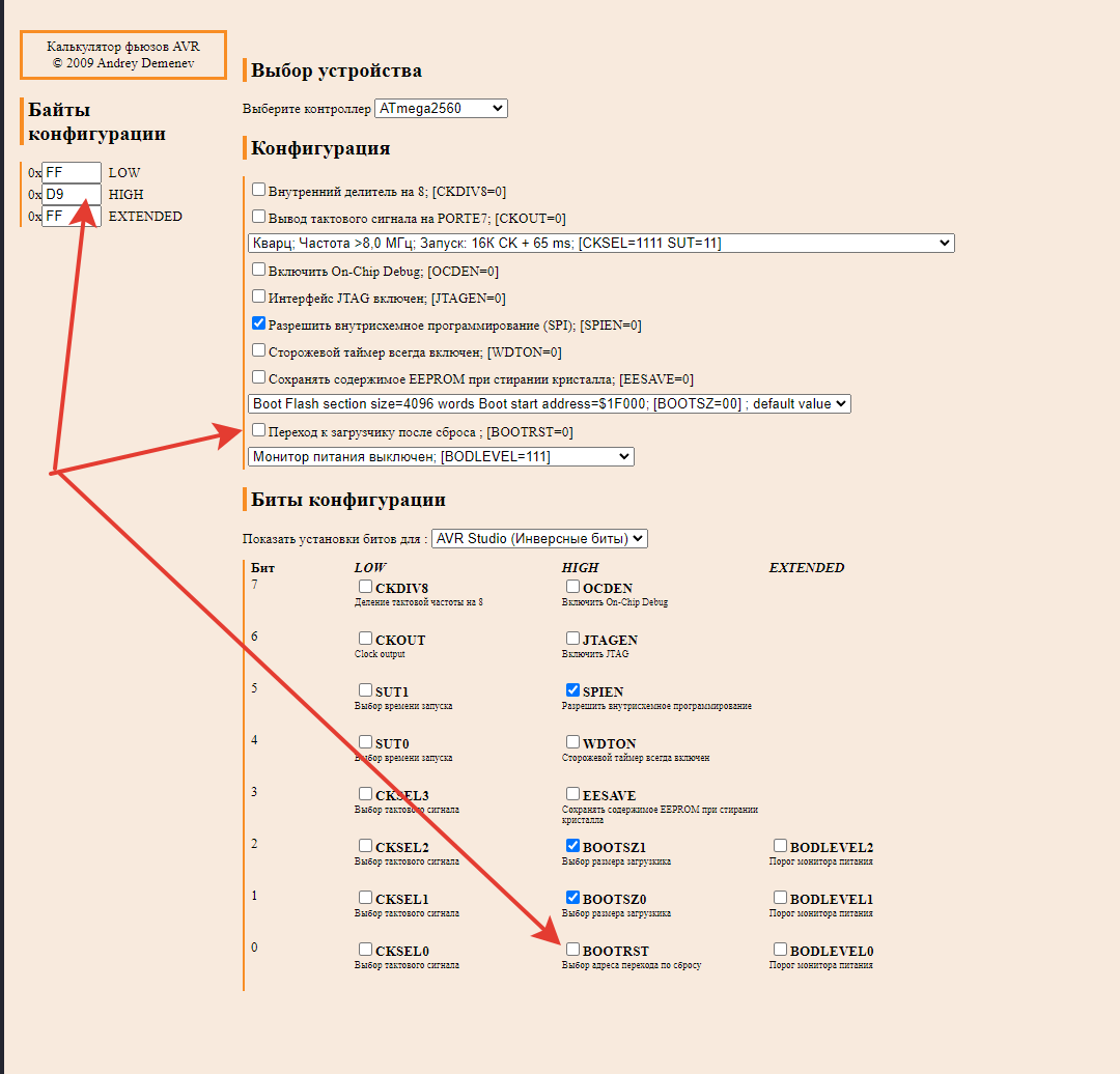
В “Прошиваем Блинк, фьюзы:”
H - 0xD8 → H - 0xD9
можешь попробывать?
да, не работает, но если с этим фьюзом 0xD9 залить прошивку без загрузчика, то блинк работает…
Шью не из IDE
када ты шьешь программатором и у тебя D8, там пусто и ничего не работает
шью ARDUINO as ISP, во фьюзах D8 и, БЛИНК РАБОТАЕТ!!!
Тут сложно не быть дураком, D9 отправляет грузится с 0 адреса, но при D8 идёт загрузка с загрузчика, загрузчик целый, это я проверял
Да, сложно тут не быть дураком или не запить ))) (но не дзен-буддистам)
Что на выхлопе, если грузимся из IDE через программатор ARDUINO as ISP скетчи работают, если через USBasp не работают