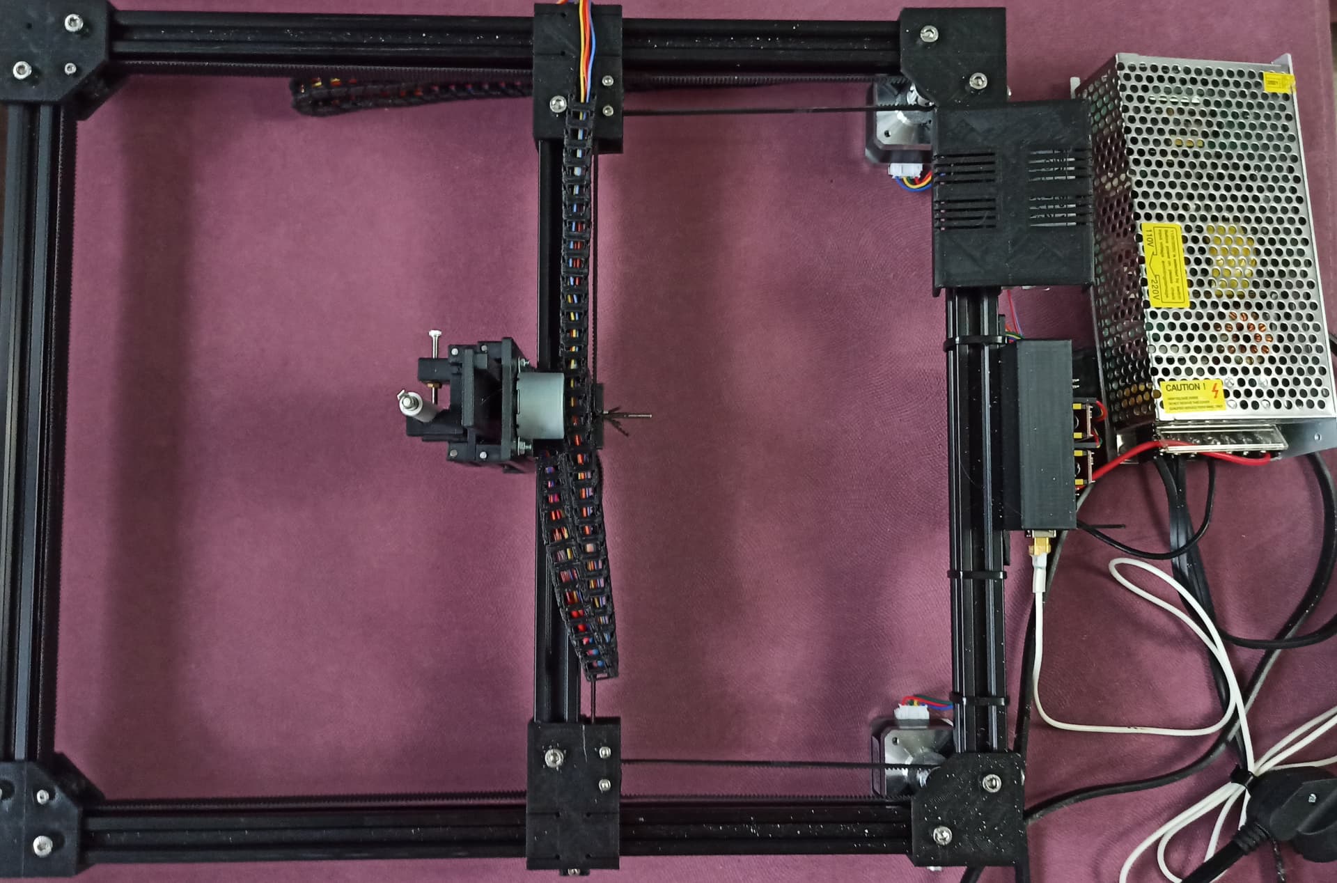
Собрал этот плоттер 2020 DRAWbot Drawing Robot by wsolstice69 - Thingiverse
Восстановил Arduino Uno из этой темы Оживление Arduino Uno
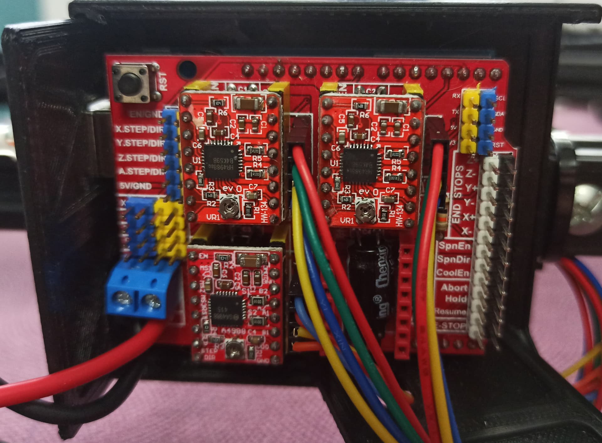
Как выяснилось, неисправный драйвер сжёг не только камень Arduino, но и все драйвера на плате расширения.
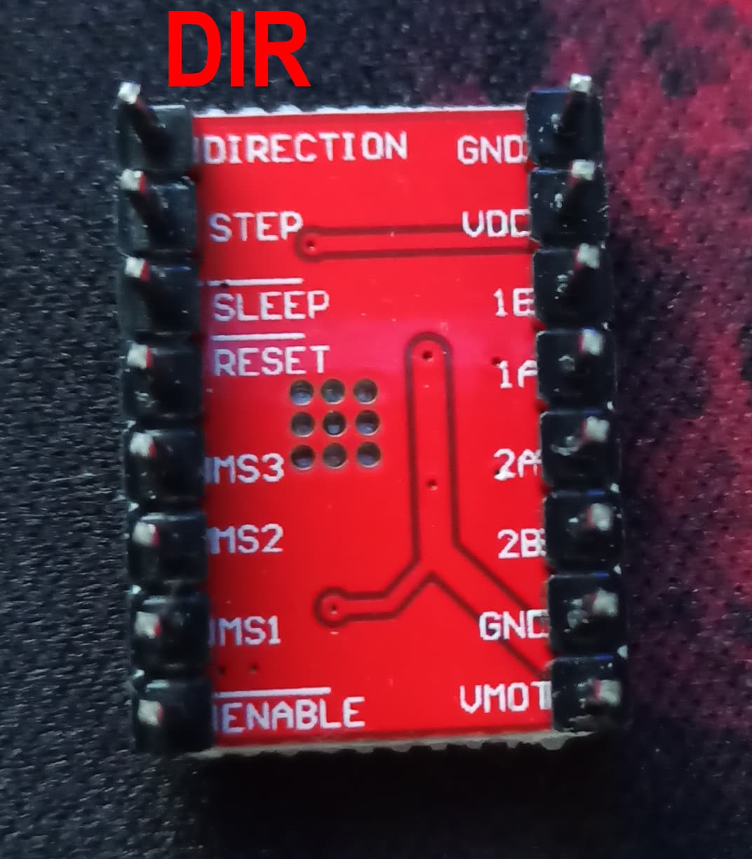
Поэтому я взял новую плату расширения и новые драйвера (A4988), на драйверах установил напряжение 0,85 вольт (на переменном smd резисторе)
Подключил к плате блок питания на 12 вольт 8 ампер, что бы плоттер ни в чём себе не отказывал.
Залил прошивку GitHub - robottini/grbl-servo: grbl 0.9i with Servo motor support · GitHub
Использовал конфигурацию автора: (строчку #define COREXY для CoreXY | Cartesian Motion Platform раскомментировал)
Спойлер
/*
  config.h - compile time configuration
  Part of Grbl

  Copyright (c) 2012-2015 Sungeun K. Jeon
  Copyright (c) 2009-2011 Simen Svale Skogsrud

  Grbl is free software: you can redistribute it and/or modify
  it under the terms of the GNU General Public License as published by
  the Free Software Foundation, either version 3 of the License, or
  (at your option) any later version.

  Grbl is distributed in the hope that it will be useful,
  but WITHOUT ANY WARRANTY; without even the implied warranty of
  MERCHANTABILITY or FITNESS FOR A PARTICULAR PURPOSE.  See the
  GNU General Public License for more details.

  You should have received a copy of the GNU General Public License
  along with Grbl.  If not, see <http://www.gnu.org/licenses/>.
*/

// This file contains compile-time configurations for Grbl's internal system. For the most part,
// users will not need to directly modify these, but they are here for specific needs, i.e.
// performance tuning or adjusting to non-typical machines.

// IMPORTANT: Any changes here requires a full re-compiling of the source code to propagate them.

#ifndef config_h
#define config_h
#include "grbl.h" // For Arduino IDE compatibility.


// Default settings. Used when resetting EEPROM. Change to desired name in defaults.h
#define DEFAULTS_GENERIC

// Serial baud rate
#define BAUD_RATE 115200

// Default cpu mappings. Grbl officially supports the Arduino Uno only. Other processor types
// may exist from user-supplied templates or directly user-defined in cpu_map.h
#define CPU_MAP_ATMEGA328P // Arduino Uno CPU

// Define realtime command special characters. These characters are 'picked-off' directly from the
// serial read data stream and are not passed to the grbl line execution parser. Select characters
// that do not and must not exist in the streamed g-code program. ASCII control characters may be
// used, if they are available per user setup. Also, extended ASCII codes (>127), which are never in
// g-code programs, maybe selected for interface programs.
// NOTE: If changed, manually update help message in report.c.
#define CMD_STATUS_REPORT '?'
#define CMD_FEED_HOLD '!'
#define CMD_CYCLE_START '~'
#define CMD_RESET 0x18 // ctrl-x.
#define CMD_SAFETY_DOOR '@'

// If homing is enabled, homing init lock sets Grbl into an alarm state upon power up. This forces
// the user to perform the homing cycle (or override the locks) before doing anything else. This is
// mainly a safety feature to remind the user to home, since position is unknown to Grbl.
//#define HOMING_INIT_LOCK // Comment to disable

// Define the homing cycle patterns with bitmasks. The homing cycle first performs a search mode
// to quickly engage the limit switches, followed by a slower locate mode, and finished by a short
// pull-off motion to disengage the limit switches. The following HOMING_CYCLE_x defines are executed
// in order starting with suffix 0 and completes the homing routine for the specified-axes only. If
// an axis is omitted from the defines, it will not home, nor will the system update its position.
// Meaning that this allows for users with non-standard cartesian machines, such as a lathe (x then z,
// with no y), to configure the homing cycle behavior to their needs.
// NOTE: The homing cycle is designed to allow sharing of limit pins, if the axes are not in the same
// cycle, but this requires some pin settings changes in cpu_map.h file. For example, the default homing
// cycle can share the Z limit pin with either X or Y limit pins, since they are on different cycles.
// By sharing a pin, this frees up a precious IO pin for other purposes. In theory, all axes limit pins
// may be reduced to one pin, if all axes are homed with seperate cycles, or vice versa, all three axes
// on separate pin, but homed in one cycle. Also, it should be noted that the function of hard limits
// will not be affected by pin sharing.
// NOTE: Defaults are set for a traditional 3-axis CNC machine. Z-axis first to clear, followed by X & Y.
#define HOMING_CYCLE_0 (1<<Z_AXIS)                // REQUIRED: First move Z to clear workspace.
#define HOMING_CYCLE_1 ((1<<X_AXIS)|(1<<Y_AXIS))  // OPTIONAL: Then move X,Y at the same time.
//#define HOMING_CYCLE_0 ((1<<X_AXIS))
//#define HOMING_CYCLE_1 ((1<<Y_AXIS))
// #define HOMING_CYCLE_2                         // OPTIONAL: Uncomment and add axes mask to enable

// Number of homing cycles performed after when the machine initially jogs to limit switches.
// This help in preventing overshoot and should improve repeatability. This value should be one or
// greater.
#define N_HOMING_LOCATE_CYCLE 1 // Integer (1-128)

// After homing, Grbl will set by default the entire machine space into negative space, as is typical
// for professional CNC machines, regardless of where the limit switches are located. Uncomment this
// define to force Grbl to always set the machine origin at the homed location despite switch orientation.
// #define HOMING_FORCE_SET_ORIGIN // Uncomment to enable.

// Number of blocks Grbl executes upon startup. These blocks are stored in EEPROM, where the size
// and addresses are defined in settings.h. With the current settings, up to 2 startup blocks may
// be stored and executed in order. These startup blocks would typically be used to set the g-code
// parser state depending on user preferences.
#define N_STARTUP_LINE 2 // Integer (1-2)

// Number of floating decimal points printed by Grbl for certain value types. These settings are
// determined by realistic and commonly observed values in CNC machines. For example, position
// values cannot be less than 0.001mm or 0.0001in, because machines can not be physically more
// precise this. So, there is likely no need to change these, but you can if you need to here.
// NOTE: Must be an integer value from 0 to ~4. More than 4 may exhibit round-off errors.
#define N_DECIMAL_COORDVALUE_INCH 4 // Coordinate or position value in inches
#define N_DECIMAL_COORDVALUE_MM   3 // Coordinate or position value in mm
#define N_DECIMAL_RATEVALUE_INCH  1 // Rate or velocity value in in/min
#define N_DECIMAL_RATEVALUE_MM    0 // Rate or velocity value in mm/min
#define N_DECIMAL_SETTINGVALUE    3 // Decimals for floating point setting values

// If your machine has two limits switches wired in parallel to one axis, you will need to enable
// this feature. Since the two switches are sharing a single pin, there is no way for Grbl to tell
// which one is enabled. This option only effects homing, where if a limit is engaged, Grbl will
// alarm out and force the user to manually disengage the limit switch. Otherwise, if you have one
// limit switch for each axis, don't enable this option. By keeping it disabled, you can perform a
// homing cycle while on the limit switch and not have to move the machine off of it.
// #define LIMITS_TWO_SWITCHES_ON_AXES

// Allows GRBL to track and report gcode line numbers.  Enabling this means that the planning buffer
// goes from 18 or 16 to make room for the additional line number data in the plan_block_t struct
// #define USE_LINE_NUMBERS // Disabled by default. Uncomment to enable.

// Allows GRBL to report the real-time feed rate.  Enabling this means that GRBL will be reporting more
// data with each status update.
// NOTE: This is experimental and doesn't quite work 100%. Maybe fixed or refactored later.
// #define REPORT_REALTIME_RATE // Disabled by default. Uncomment to enable.

// Upon a successful probe cycle, this option provides immediately feedback of the probe coordinates
// through an automatically generated message. If disabled, users can still access the last probe
// coordinates through Grbl '$#' print parameters.
#define MESSAGE_PROBE_COORDINATES // Enabled by default. Comment to disable.

// Enables a second coolant control pin via the mist coolant g-code command M7 on the Arduino Uno
// analog pin 5. Only use this option if you require a second coolant control pin.
// NOTE: The M8 flood coolant control pin on analog pin 4 will still be functional regardless.
// #define ENABLE_M7 // Disabled by default. Uncomment to enable.

// This option causes the feed hold input to act as a safety door switch. A safety door, when triggered,
// immediately forces a feed hold and then safely de-energizes the machine. Resuming is blocked until
// the safety door is re-engaged. When it is, Grbl will re-energize the machine and then resume on the
// previous tool path, as if nothing happened.
// #define ENABLE_SAFETY_DOOR_INPUT_PIN // Default disabled. Uncomment to enable.

// After the safety door switch has been toggled and restored, this setting sets the power-up delay
// between restoring the spindle and coolant and resuming the cycle.
// NOTE: Delay value is defined in milliseconds from zero to 65,535.
#define SAFETY_DOOR_SPINDLE_DELAY 4000
#define SAFETY_DOOR_COOLANT_DELAY 1000

// Enable CoreXY kinematics. Use ONLY with CoreXY machines.
// IMPORTANT: If homing is enabled, you must reconfigure the homing cycle #defines above to
// #define HOMING_CYCLE_0 (1<<X_AXIS) and #define HOMING_CYCLE_1 (1<<Y_AXIS)
// NOTE: This configuration option alters the motion of the X and Y axes to principle of operation
// defined at (http://corexy.com/theory.html). Motors are assumed to positioned and wired exactly as
// described, if not, motions may move in strange directions. Grbl assumes the CoreXY A and B motors
// have the same steps per mm internally.
#define COREXY // Default disabled. Uncomment to enable.

// Inverts pin logic of the control command pins. This essentially means when this option is enabled
// you can use normally-closed switches, rather than the default normally-open switches.
// NOTE: Will eventually be added to Grbl settings in v1.0.
// #define INVERT_CONTROL_PIN // Default disabled. Uncomment to enable.

// Inverts the spindle enable pin from low-disabled/high-enabled to low-enabled/high-disabled. Useful
// for some pre-built electronic boards.
// NOTE: If VARIABLE_SPINDLE is enabled(default), this option has no effect as the PWM output and
// spindle enable are combined to one pin. If you need both this option and spindle speed PWM,
// uncomment the config option USE_SPINDLE_DIR_AS_ENABLE_PIN below.
// #define INVERT_SPINDLE_ENABLE_PIN // Default disabled. Uncomment to enable.

// Enable control pin states feedback in status reports. The data is presented as simple binary of
// the control pin port (0 (low) or 1(high)), masked to show only the input pins. Non-control pins on the
// port will always show a 0 value. See cpu_map.h for the pin bitmap. As with the limit pin reporting,
// we do not recommend keeping this option enabled. Try to only use this for setting up a new CNC.
// #define REPORT_CONTROL_PIN_STATE // Default disabled. Uncomment to enable.

// When Grbl powers-cycles or is hard reset with the Arduino reset button, Grbl boots up with no ALARM
// by default. This is to make it as simple as possible for new users to start using Grbl. When homing
// is enabled and a user has installed limit switches, Grbl will boot up in an ALARM state to indicate
// Grbl doesn't know its position and to force the user to home before proceeding. This option forces
// Grbl to always initialize into an ALARM state regardless of homing or not. This option is more for
// OEMs and LinuxCNC users that would like this power-cycle behavior.
// #define FORCE_INITIALIZATION_ALARM // Default disabled. Uncomment to enable.

// ---------------------------------------------------------------------------------------
// ADVANCED CONFIGURATION OPTIONS:

// Enables minimal reporting feedback mode for GUIs, where human-readable strings are not as important.
// This saves nearly 2KB of flash space and may allow enough space to install other/future features.
// GUIs will need to install a look-up table for the error-codes that Grbl sends back in their place.
// NOTE: This feature is new and experimental. Make sure the GUI you are using supports this mode.
// #define REPORT_GUI_MODE // Default disabled. Uncomment to enable.

// The temporal resolution of the acceleration management subsystem. A higher number gives smoother
// acceleration, particularly noticeable on machines that run at very high feedrates, but may negatively
// impact performance. The correct value for this parameter is machine dependent, so it's advised to
// set this only as high as needed. Approximate successful values can widely range from 50 to 200 or more.
// NOTE: Changing this value also changes the execution time of a segment in the step segment buffer.
// When increasing this value, this stores less overall time in the segment buffer and vice versa. Make
// certain the step segment buffer is increased/decreased to account for these changes.
#define ACCELERATION_TICKS_PER_SECOND 100

// Adaptive Multi-Axis Step Smoothing (AMASS) is an advanced feature that does what its name implies,
// smoothing the stepping of multi-axis motions. This feature smooths motion particularly at low step
// frequencies below 10kHz, where the aliasing between axes of multi-axis motions can cause audible
// noise and shake your machine. At even lower step frequencies, AMASS adapts and provides even better
// step smoothing. See stepper.c for more details on the AMASS system works.
#define ADAPTIVE_MULTI_AXIS_STEP_SMOOTHING  // Default enabled. Comment to disable.

// Sets the maximum step rate allowed to be written as a Grbl setting. This option enables an error
// check in the settings module to prevent settings values that will exceed this limitation. The maximum
// step rate is strictly limited by the CPU speed and will change if something other than an AVR running
// at 16MHz is used.
// NOTE: For now disabled, will enable if flash space permits.
// #define MAX_STEP_RATE_HZ 30000 // Hz

// By default, Grbl sets all input pins to normal-high operation with their internal pull-up resistors
// enabled. This simplifies the wiring for users by requiring only a switch connected to ground,
// although its recommended that users take the extra step of wiring in low-pass filter to reduce
// electrical noise detected by the pin. If the user inverts the pin in Grbl settings, this just flips
// which high or low reading indicates an active signal. In normal operation, this means the user
// needs to connect a normal-open switch, but if inverted, this means the user should connect a
// normal-closed switch.
// The following options disable the internal pull-up resistors, sets the pins to a normal-low
// operation, and switches must be now connect to Vcc instead of ground. This also flips the meaning
// of the invert pin Grbl setting, where an inverted setting now means the user should connect a
// normal-open switch and vice versa.
// NOTE: All pins associated with the feature are disabled, i.e. XYZ limit pins, not individual axes.
// WARNING: When the pull-ups are disabled, this requires additional wiring with pull-down resistors!
//#define DISABLE_LIMIT_PIN_PULL_UP
//#define DISABLE_PROBE_PIN_PULL_UP
//#define DISABLE_CONTROL_PIN_PULL_UP

// Sets which axis the tool length offset is applied. Assumes the spindle is always parallel with
// the selected axis with the tool oriented toward the negative direction. In other words, a positive
// tool length offset value is subtracted from the current location.
#define TOOL_LENGTH_OFFSET_AXIS Z_AXIS // Default z-axis. Valid values are X_AXIS, Y_AXIS, or Z_AXIS.

// Enables variable spindle output voltage for different RPM values. On the Arduino Uno, the spindle
// enable pin will output 5V for maximum RPM with 256 intermediate levels and 0V when disabled.
// NOTE: IMPORTANT for Arduino Unos! When enabled, the Z-limit pin D11 and spindle enable pin D12 switch!
// The hardware PWM output on pin D11 is required for variable spindle output voltages.
#define VARIABLE_SPINDLE // Default enabled. Comment to disable.

// Used by the variable spindle output only. These parameters set the maximum and minimum spindle speed
// "S" g-code values to correspond to the maximum and minimum pin voltages. There are 256 discrete and
// equally divided voltage bins between the maximum and minimum spindle speeds. So for a 5V pin, 1000
// max rpm, and 250 min rpm, the spindle output voltage would be set for the following "S" commands:
// "S1000" @ 5V, "S250" @ 0.02V, and "S625" @ 2.5V (mid-range). The pin outputs 0V when disabled.
#define SPINDLE_MAX_RPM 90 // Max spindle RPM. This value is equal to 100% duty cycle on the PWM.
#define SPINDLE_MIN_RPM 0.0    // Min spindle RPM. This value is equal to (1/256) duty cycle on the PWM.

// Used by variable spindle output only. This forces the PWM output to a minimum duty cycle when enabled.
// When disabled, the PWM pin will still read 0V. Most users will not need this option, but it may be
// useful in certain scenarios. This setting does not update the minimum spindle RPM calculations. Any
// spindle RPM output lower than this value will be set to this value.
// #define MINIMUM_SPINDLE_PWM 5 // Default disabled. Uncomment to enable. Integer (0-255)

// By default on a 328p(Uno), Grbl combines the variable spindle PWM and the enable into one pin to help
// preserve I/O pins. For certain setups, these may need to be separate pins. This configure option uses
// the spindle direction pin(D13) as a separate spindle enable pin along with spindle speed PWM on pin D11.
// NOTE: This configure option only works with VARIABLE_SPINDLE enabled and a 328p processor (Uno).
// NOTE: With no direction pin, the spindle clockwise M4 g-code command will be removed. M3 and M5 still work.
//#define USE_SPINDLE_DIR_AS_ENABLE_PIN // Default disabled. Uncomment to enable.

// With this enabled, Grbl sends back an echo of the line it has received, which has been pre-parsed (spaces
// removed, capitalized letters, no comments) and is to be immediately executed by Grbl. Echoes will not be
// sent upon a line buffer overflow, but should for all normal lines sent to Grbl. For example, if a user
// sendss the line 'g1 x1.032 y2.45 (test comment)', Grbl will echo back in the form '[echo: G1X1.032Y2.45]'.
// NOTE: Only use this for debugging purposes!! When echoing, this takes up valuable resources and can effect
// performance. If absolutely needed for normal operation, the serial write buffer should be greatly increased
// to help minimize transmission waiting within the serial write protocol.
// #define REPORT_ECHO_LINE_RECEIVED // Default disabled. Uncomment to enable.

// Minimum planner junction speed. Sets the default minimum junction speed the planner plans to at
// every buffer block junction, except for starting from rest and end of the buffer, which are always
// zero. This value controls how fast the machine moves through junctions with no regard for acceleration
// limits or angle between neighboring block line move directions. This is useful for machines that can't
// tolerate the tool dwelling for a split second, i.e. 3d printers or laser cutters. If used, this value
// should not be much greater than zero or to the minimum value necessary for the machine to work.
#define MINIMUM_JUNCTION_SPEED 0.0 // (mm/min)

// Sets the minimum feed rate the planner will allow. Any value below it will be set to this minimum
// value. This also ensures that a planned motion always completes and accounts for any floating-point
// round-off errors. Although not recommended, a lower value than 1.0 mm/min will likely work in smaller
// machines, perhaps to 0.1mm/min, but your success may vary based on multiple factors.
#define MINIMUM_FEED_RATE 1.0 // (mm/min)

// Number of arc generation iterations by small angle approximation before exact arc trajectory
// correction with expensive sin() and cos() calcualtions. This parameter maybe decreased if there
// are issues with the accuracy of the arc generations, or increased if arc execution is getting
// bogged down by too many trig calculations.
#define N_ARC_CORRECTION 12 // Integer (1-255)

// The arc G2/3 g-code standard is problematic by definition. Radius-based arcs have horrible numerical
// errors when arc at semi-circles(pi) or full-circles(2*pi). Offset-based arcs are much more accurate
// but still have a problem when arcs are full-circles (2*pi). This define accounts for the floating
// point issues when offset-based arcs are commanded as full circles, but get interpreted as extremely
// small arcs with around machine epsilon (1.2e-7rad) due to numerical round-off and precision issues.
// This define value sets the machine epsilon cutoff to determine if the arc is a full-circle or not.
// NOTE: Be very careful when adjusting this value. It should always be greater than 1.2e-7 but not too
// much greater than this. The default setting should capture most, if not all, full arc error situations.
#define ARC_ANGULAR_TRAVEL_EPSILON 5E-7 // Float (radians)

// Time delay increments performed during a dwell. The default value is set at 50ms, which provides
// a maximum time delay of roughly 55 minutes, more than enough for most any application. Increasing
// this delay will increase the maximum dwell time linearly, but also reduces the responsiveness of
// run-time command executions, like status reports, since these are performed between each dwell
// time step. Also, keep in mind that the Arduino delay timer is not very accurate for long delays.
#define DWELL_TIME_STEP 50 // Integer (1-255) (milliseconds)

// Creates a delay between the direction pin setting and corresponding step pulse by creating
// another interrupt (Timer2 compare) to manage it. The main Grbl interrupt (Timer1 compare)
// sets the direction pins, and does not immediately set the stepper pins, as it would in
// normal operation. The Timer2 compare fires next to set the stepper pins after the step
// pulse delay time, and Timer2 overflow will complete the step pulse, except now delayed
// by the step pulse time plus the step pulse delay. (Thanks langwadt for the idea!)
// NOTE: Uncomment to enable. The recommended delay must be > 3us, and, when added with the
// user-supplied step pulse time, the total time must not exceed 127us. Reported successful
// values for certain setups have ranged from 5 to 20us.
// #define STEP_PULSE_DELAY 10 // Step pulse delay in microseconds. Default disabled.

// The number of linear motions in the planner buffer to be planned at any give time. The vast
// majority of RAM that Grbl uses is based on this buffer size. Only increase if there is extra
// available RAM, like when re-compiling for a Mega or Sanguino. Or decrease if the Arduino
// begins to crash due to the lack of available RAM or if the CPU is having trouble keeping
// up with planning new incoming motions as they are executed.
// #define BLOCK_BUFFER_SIZE 18  // Uncomment to override default in planner.h.

// Governs the size of the intermediary step segment buffer between the step execution algorithm
// and the planner blocks. Each segment is set of steps executed at a constant velocity over a
// fixed time defined by ACCELERATION_TICKS_PER_SECOND. They are computed such that the planner
// block velocity profile is traced exactly. The size of this buffer governs how much step
// execution lead time there is for other Grbl processes have to compute and do their thing
// before having to come back and refill this buffer, currently at ~50msec of step moves.
// #define SEGMENT_BUFFER_SIZE 6 // Uncomment to override default in stepper.h.

// Line buffer size from the serial input stream to be executed. Also, governs the size of
// each of the startup blocks, as they are each stored as a string of this size. Make sure
// to account for the available EEPROM at the defined memory address in settings.h and for
// the number of desired startup blocks.
// NOTE: 80 characters is not a problem except for extreme cases, but the line buffer size
// can be too small and g-code blocks can get truncated. Officially, the g-code standards
// support up to 256 characters. In future versions, this default will be increased, when
// we know how much extra memory space we can re-invest into this.
// #define LINE_BUFFER_SIZE 80  // Uncomment to override default in protocol.h

// Serial send and receive buffer size. The receive buffer is often used as another streaming
// buffer to store incoming blocks to be processed by Grbl when its ready. Most streaming
// interfaces will character count and track each block send to each block response. So,
// increase the receive buffer if a deeper receive buffer is needed for streaming and avaiable
// memory allows. The send buffer primarily handles messages in Grbl. Only increase if large
// messages are sent and Grbl begins to stall, waiting to send the rest of the message.
// NOTE: Buffer size values must be greater than zero and less than 256.
// #define RX_BUFFER_SIZE 128 // Uncomment to override defaults in serial.h
// #define TX_BUFFER_SIZE 64

// Toggles XON/XOFF software flow control for serial communications. Not officially supported
// due to problems involving the Atmega8U2 USB-to-serial chips on current Arduinos. The firmware
// on these chips do not support XON/XOFF flow control characters and the intermediate buffer
// in the chips cause latency and overflow problems with standard terminal programs. However,
// using specifically-programmed UI's to manage this latency problem has been confirmed to work.
// As well as, older FTDI FT232RL-based Arduinos(Duemilanove) are known to work with standard
// terminal programs since their firmware correctly manage these XON/XOFF characters. In any
// case, please report any successes to grbl administrators!
// #define ENABLE_XONXOFF // Default disabled. Uncomment to enable.

// A simple software debouncing feature for hard limit switches. When enabled, the interrupt
// monitoring the hard limit switch pins will enable the Arduino's watchdog timer to re-check
// the limit pin state after a delay of about 32msec. This can help with CNC machines with
// problematic false triggering of their hard limit switches, but it WILL NOT fix issues with
// electrical interference on the signal cables from external sources. It's recommended to first
// use shielded signal cables with their shielding connected to ground (old USB/computer cables
// work well and are cheap to find) and wire in a low-pass circuit into each limit pin.
// #define ENABLE_SOFTWARE_DEBOUNCE // Default disabled. Uncomment to enable.

// Force Grbl to check the state of the hard limit switches when the processor detects a pin
// change inside the hard limit ISR routine. By default, Grbl will trigger the hard limits
// alarm upon any pin change, since bouncing switches can cause a state check like this to
// misread the pin. When hard limits are triggered, they should be 100% reliable, which is the
// reason that this option is disabled by default. Only if your system/electronics can guarantee
// that the switches don't bounce, we recommend enabling this option. This will help prevent
// triggering a hard limit when the machine disengages from the switch.
// NOTE: This option has no effect if SOFTWARE_DEBOUNCE is enabled.
// #define HARD_LIMIT_FORCE_STATE_CHECK // Default disabled. Uncomment to enable.


// ---------------------------------------------------------------------------------------
// COMPILE-TIME ERROR CHECKING OF DEFINE VALUES:

#ifndef HOMING_CYCLE_0
  #error "Required HOMING_CYCLE_0 not defined."
#endif

#if defined(USE_SPINDLE_DIR_AS_ENABLE_PIN) && !defined(VARIABLE_SPINDLE)
  #error "USE_SPINDLE_DIR_AS_ENABLE_PIN may only be used with VARIABLE_SPINDLE enabled"
#endif

#if defined(USE_SPINDLE_DIR_AS_ENABLE_PIN) && !defined(CPU_MAP_ATMEGA328P)
  #error "USE_SPINDLE_DIR_AS_ENABLE_PIN may only be used with a 328p processor"
#endif

// ---------------------------------------------------------------------------------------


#endif
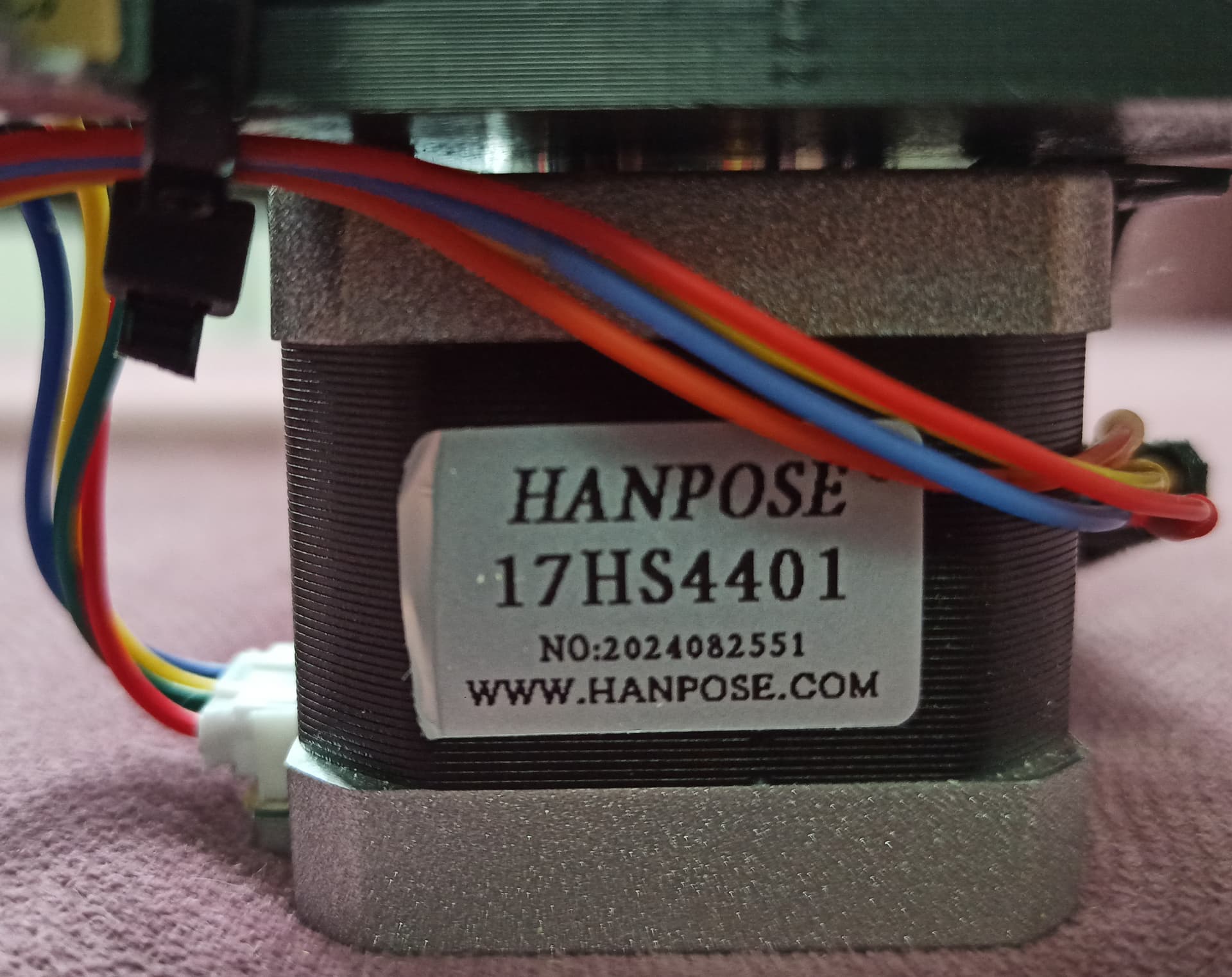
Сервоприводы которые я использую:
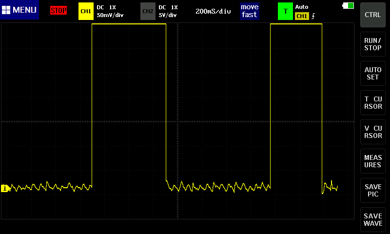
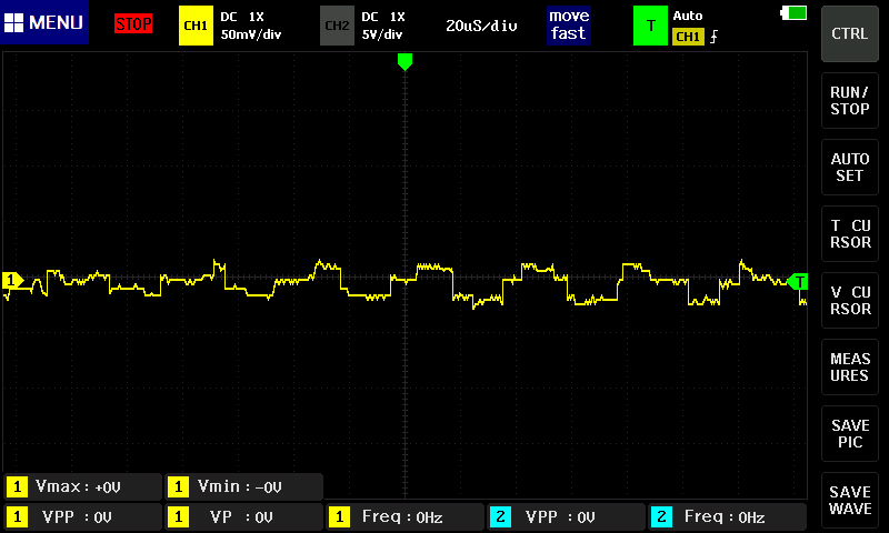
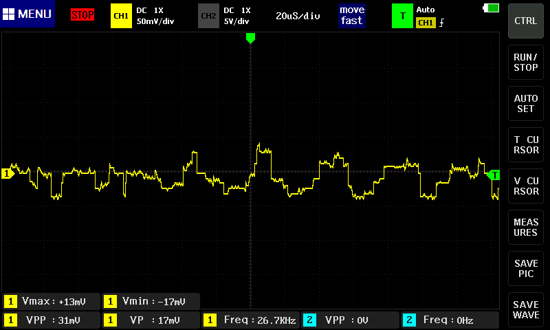
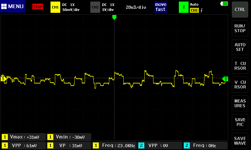
Однако, какие бы я кнопки на пульте Univarsal Gcode Sender (Version 2.1.12) не нажимал,
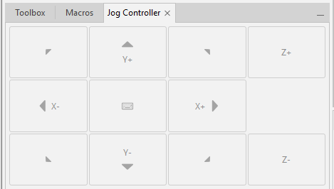
сервоприводы крутятся только в одну сторону, при этом если перевернуть штекеры, то они начинают крутиться только в другую.
Штекеры я паял сам, прозвонил обмотки и собрал их попарно.
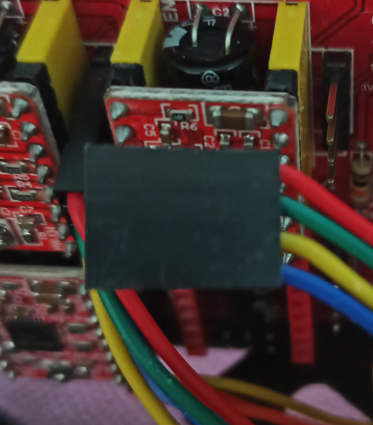
Так как я до этого момента не разу не имел дел с сервоприводами и драйверами для них, я не знаю куда копать, что бы сервоприводы адекватно реагировали на команды и крутились в обе стороны.
Поэтому решил спросить совета у Вас уважаемые форумчане?